Torsional vibration suppressing method and apparatus in electric motor speed control system

a technology of electric motor speed control and torsional vibration, which is applied in the direction of motor/generator/converter stopper, dynamo-electric converter control, instruments, etc., can solve the problems of insufficient suppression effect and insufficient suppression effect of equipment, and achieve the effect of sufficient suppression

Inactive Publication Date: 2007-03-13
YASKAWA DENKI KK
View PDF5 Cites 8 Cited by
  • Summary
  • Abstract
  • Description
  • Claims
  • Application Information

AI Technical Summary

Benefits of technology

[0014]Therefore, it is an object of the invention to provide a torsional vibration suppressing method and apparatus in an electric motor speed control system which can sufficiently suppress a periodic and feeble fluctuation in the speed or acceleration of a load and a periodic and feeble fluctuation in the torque of a driving shaft.
[0019]According to the second invention, moreover, the proportional gain G2 of the inertia controller 29 is set to have a positive value and the inertia of the electric motor portion is enlarged to be equivalently (1+G2)-fold, thereby carrying out the control in the first invention, while the proportional gain G2 of the inertia controller 29 is set to have a negative value of 0 to −1 and is thus used. By controlling the inertia of the electric motor portion corresponding to the magnitude of the inertia which is suitable for a mechanical system, consequently, it is possible to enhance the stability of the control.

Problems solved by technology

In the case in which a periodic fluctuation in the speed or acceleration of a load or a periodic fluctuation in the torque of a driving shaft is feeble, a sufficient suppressing effect cannot be obtained.
For this reason, there is a problem in that a sufficient suppressing effect cannot be obtained in equipment in which the generation of a feeble and periodic fluctuation is not permitted to the speed or acceleration of a load, for example, the acceleration vibration of an elevator cage or a periodic fluctuation in the speed of a print roll of a printing machine.

Method used


Image

  • Torsional vibration suppressing method and apparatus in electric motor speed control system
  • Torsional vibration suppressing method and apparatus in electric motor speed control system
  • Torsional vibration suppressing method and apparatus in electric motor speed control system

Examples


first embodiment

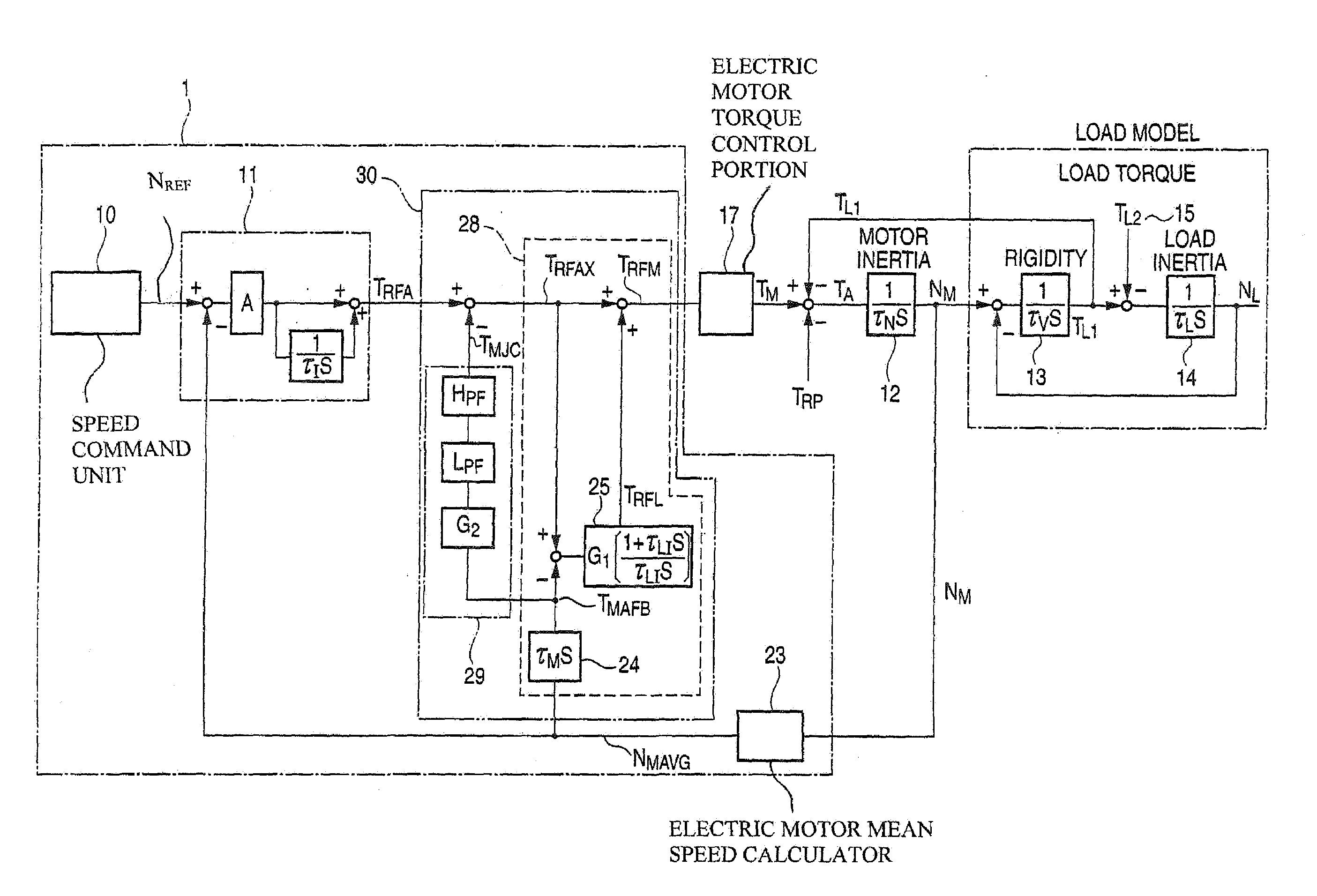
[0055]FIG. 1 is a block diagram showing the torsional vibration suppressing device of an electric motor speed control system according to the invention.

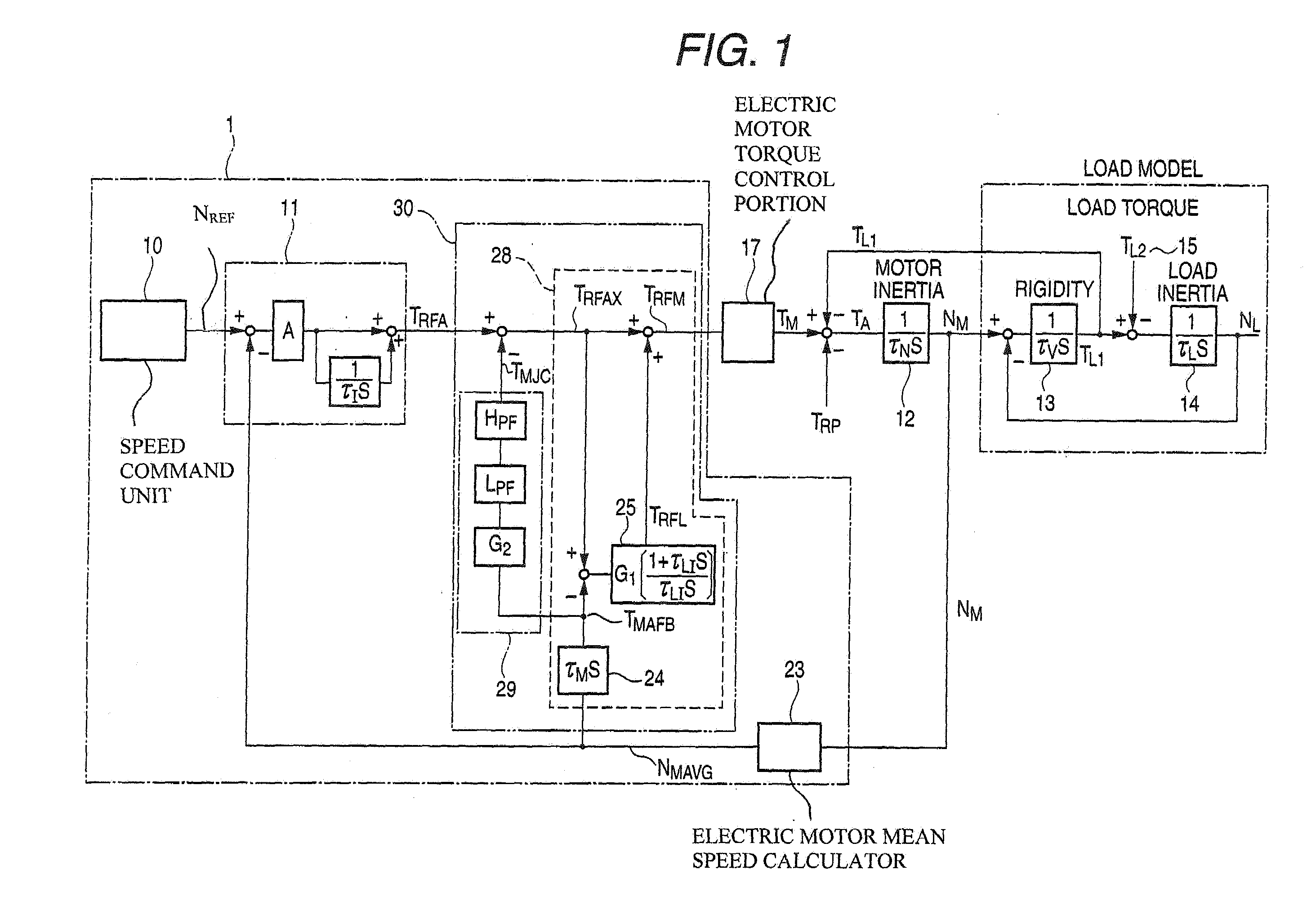
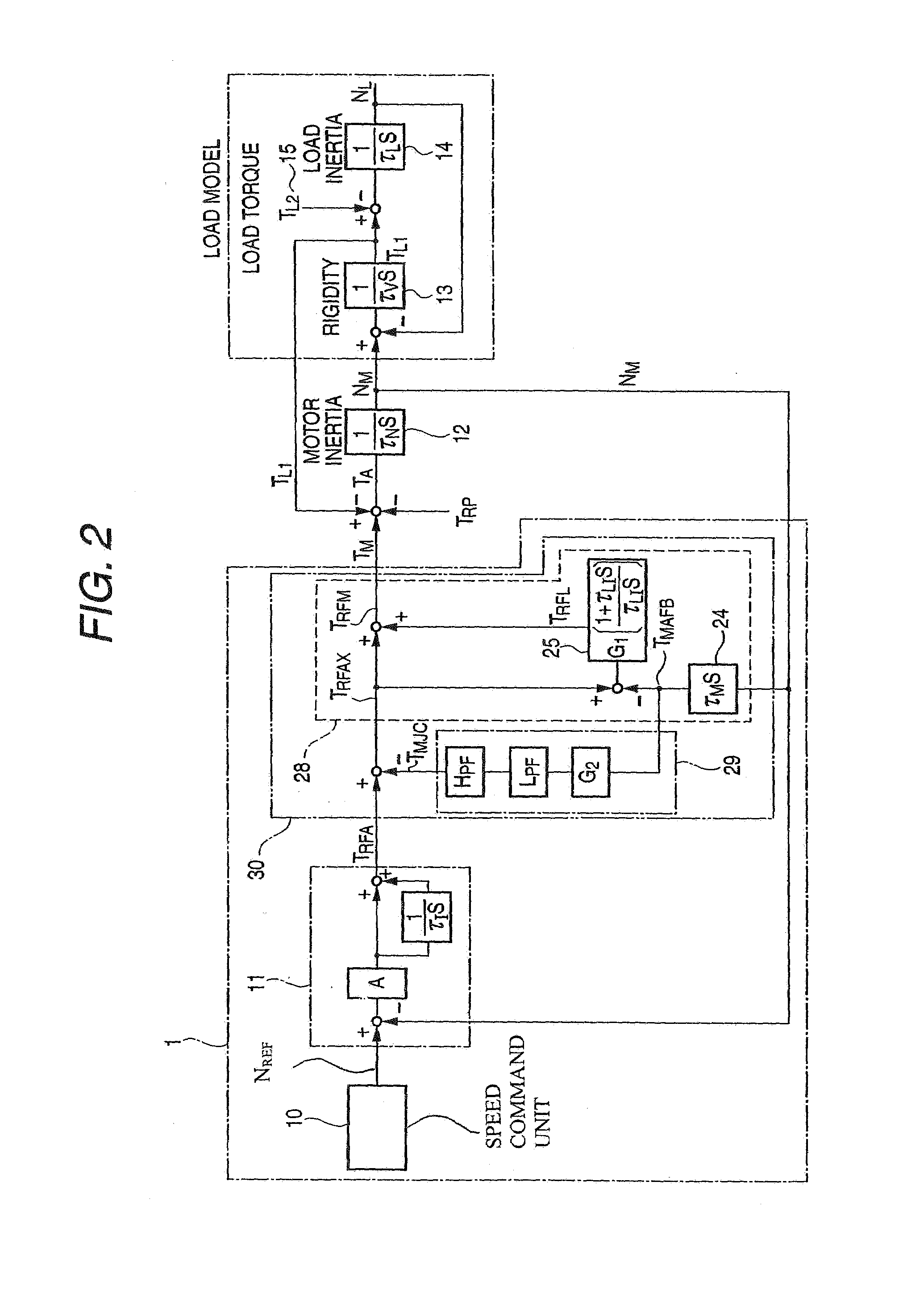
[0056]FIG. 2 is a control block diagram showing the control concept of the device illustrated in FIG. 1.

[0057]FIG. 3 is a diagram showing the control principle of the control block illustrating the control concept in FIG. 2.

[0058]In FIG. 1, 29 denotes an inertia controller which is constituted by a proportional gain G2, a low-pass filter LPF and a high-pass filter HPF. A vibration suppressing control portion 30 is constituted by a torsional vibration suppressing control portion 28 and the inertia controller 29.

[0059]The same other structures as those in the conventional drawing of FIG. 5 have the same reference numerals and the repetitive description of the structures will be omitted.

[0060]Next, an operation will be described.

[0061]FIG. 2 is a control block diagram in which the mean speed calculator 23 in the electric motor and the t...

second embodiment

[0068]Next, the invention will be described with reference to the drawings.

[0069]In each of the drawings, the first embodiment is common to the second embodiment, and a control structure according to the second embodiment is entirely identical to that in FIG. 1.

[0070]As described above, in the block shown in FIG. 3, the equation related to the electric motor speed NM can be represented as the Equation (2). On the other hand, the equation related to the electric motor speed NM in the block of FIG. 2 can be represented as the Equation (3). The Equations (2) and (3) are entirely identical to each other. Therefore, the block provided with the inertia controller 29 according to the invention shown in FIG. 1 can be controlled in such a manner that the inertia of the electric motor is approximately (1+G2)-fold.

[0071]By this principle, the proportional gain G2 of the inertia controller 29 is set to have a positive value to equivalently enlarge the inertia of the electric motor portion to be...


PUM


Abstract

It is an object of the invention to provide a torsional vibration suppressing apparatus further including an inertia control portion capable of suppressing a feeble vibration in a torsional vibration suppressing control portion.The invention includes inertia control means (29) for calculating and outputting an inertia control signal TMJC from an electric motor acceleration torque signal TMAFB obtained by multiplying a signal acquired by differentiating an electric motor mean speed signal NMAVG by an inertia time constant τM of the electric motor portion, electric motor acceleration torque control means (28) for calculating a torque command compensation signal TRFL from a deviation signal of a signal TRFAX obtained by decreasing TMJC from a torque command signal TRFA and the electric motor acceleration torque signal TMAFB, and electric motor torque control means for controlling a current of the electric motor in order to obtain an electric motor torque in accordance with a torque command TRFM to be a sum of TRFA and TRFL.

Description

TECHNICAL FIELD[0001]The present invention relates to the suppression of a resonance in a driving system to be a 2-inertia system or a multi-inertia system which has a resonant system, and more particularly to a method of suppressing the vibration of an electric motor which is improved to obtain a sufficient suppressing effect for a feeble vibration caused by the pulsating torque of the electric motor or a periodic fluctuation in a load, and a control apparatus.BACKGROUND ART[0002]Examples of a conventional vibration suppressing method include “a method of suppressing a torsional vibration in an electric motor speed control system” disclosed in Patent Document 1.[0003]FIG. 4 is a mechanical diagram showing a general variable speed driving device, and a rotating torque is transmitted to a machine 5 through a driving shaft 4 having a torsional rigidity rate K (Kgm / rad) by means of an electric motor 2. A variable speed control device 1 controls the speed of the electric motor 2 by sett...

Claims


Application Information

Patent Timeline
Patent Type & Authority Patents(United States)
IPC IPC(8): H02P7/00H02P29/00
CPCH02P29/0038H02P29/50
Inventor SHIBATA, NAOTAKESONODA, KEISUKEIKEGUCHI, MASAOTOUJINBARA, HIROTAKA
Owner YASKAWA DENKI KK
Why Eureka
Try Eureka