Method of making a hyperboloid electrical contact

Inactive Publication Date: 2007-03-20
QA TECHNOLOGIES
View PDF61 Cites 31 Cited by
  • Summary
  • Abstract
  • Description
  • Claims
  • Application Information

AI Technical Summary

Benefits of technology

[0004]In accordance with the present invention, a hyperboloid contact socket is provided which can be manufactured in a cost efficient manner using automated high speed manufacturing processes and wherein different types of terminations can be affixed to the contact socket as desirable for user requirements. The contact socket comprises a tubular body of metal or other suitable conductive material and preferably having at one end a lip defining an entrance aperture for receiving a mating pin terminal and having on the opposite end a termination of an intended configuration for attachment to a circuit board or other device or item. The tubular body contains a plurality of conductive wires welded or otherwise conductively and permanently affixed at their respective ends to respective inner surfaces at or near th

Problems solved by technology

This contact configuration has been in use for many years and is known to present a difficult assembly task and to require expensive, high precision machined components.
Additionally, due to the nature of the press fit retention of the wires, it is not uncommon for the wires to become separated from within the inner and outer sleeves, particularly during usage of the contact, thereby leading to field failures of the device in which it is in use.
Additionally, this type of field failure can lead to damage of the mating

Method used


Image

  • Method of making a hyperboloid electrical contact
  • Method of making a hyperboloid electrical contact
  • Method of making a hyperboloid electrical contact

Examples


Embodiment Construction

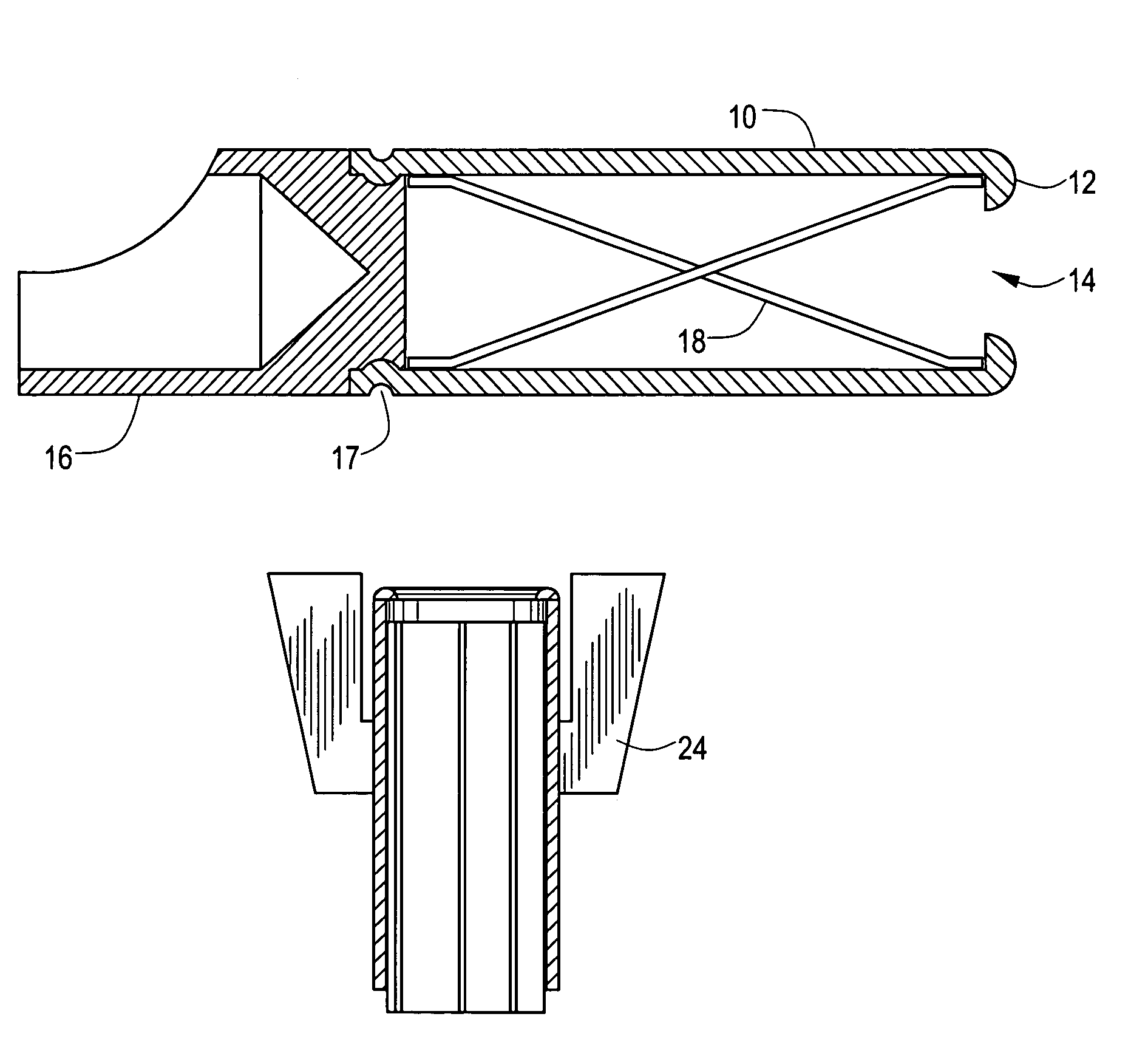
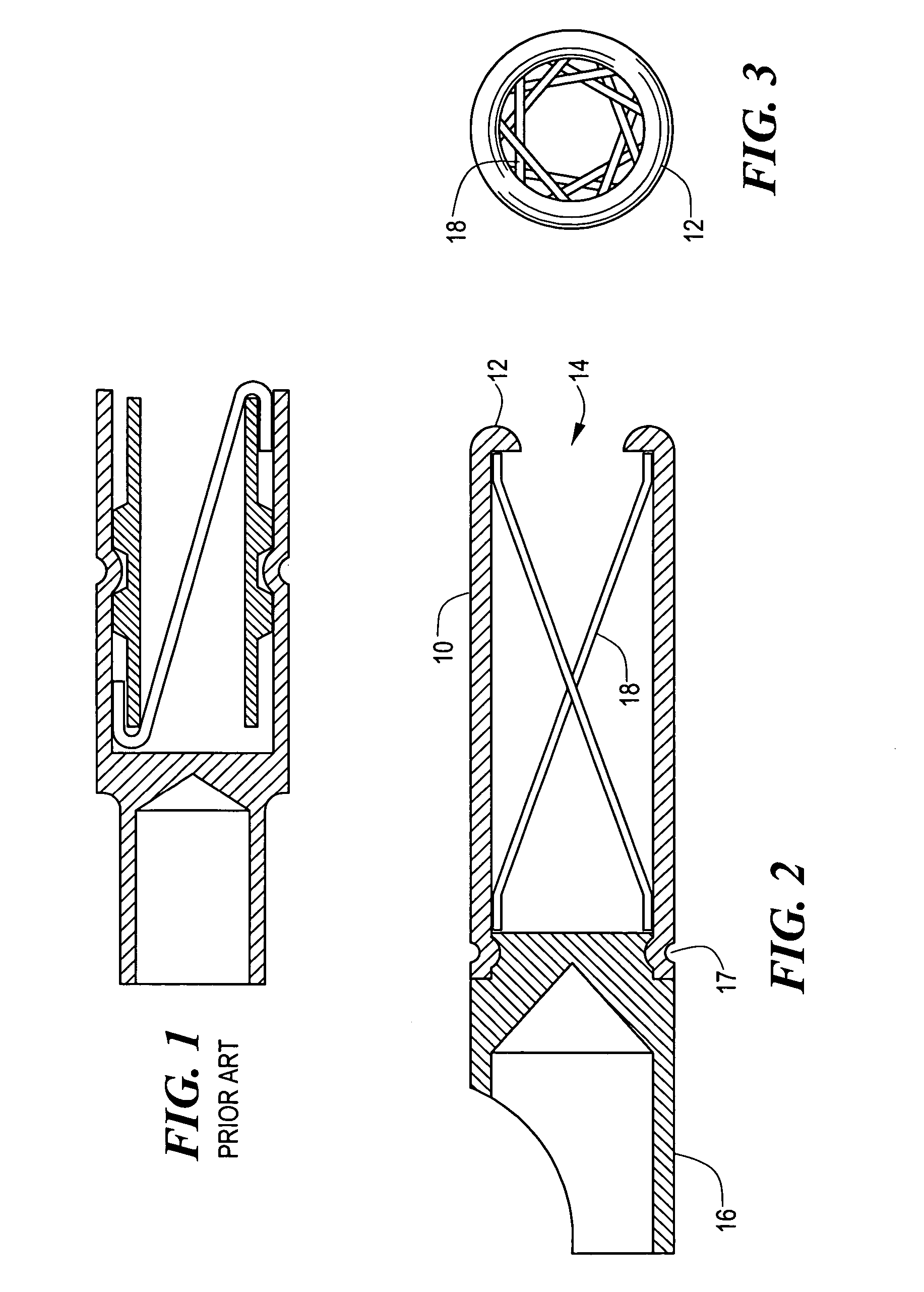
[0041]Referring to FIGS. 2 and 3 there is shown a contact socket in accordance with the invention which comprises a tubular body 10 of a suitable metal or other conductive material and having a lip 12 defining an aperture 14 for receiving a mating pin terminal, and having a termination 16 for attachment to a circuit board or other item. The tubular body contains a plurality of conductive wires 18 welded or otherwise conductively and permanently affixed at their respective ends to the outer and inner ends of the body and disposed in an angular disposition to the longitudinal axis to form a hyperboloid shape. In the illustrated embodiment, the body 10 is attached to termination 16 at juncture 17 by rolling, crimping, swaging or other suitable means to provide mechanical and conductive attachment.

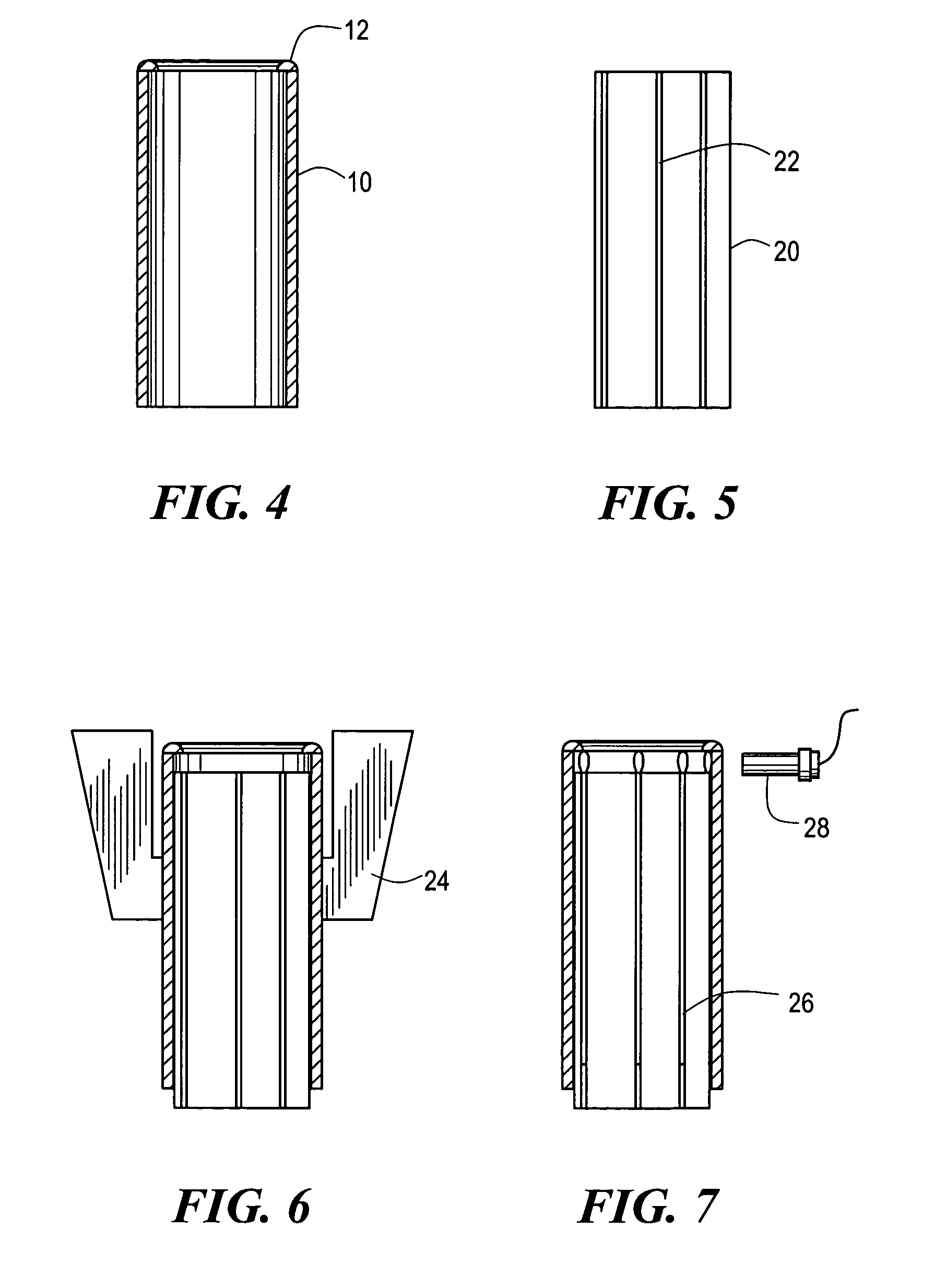
[0042]The method of making the contact socket will be described in conjunction with FIGS. 4–9. FIG. 4 shows a tubular body 10 preferably having a lip 12. In FIG. 5 there is shown a mandrel 20 ...


PUM

PropertyMeasurementUnit
Lengthaaaaaaaaaa
Electrical conductivityaaaaaaaaaa
Shapeaaaaaaaaaa

Abstract

A hyperboloid contact socket is provided which comprises a tubular body of conductive material and preferably having at one end a lip defining an entrance aperture for receiving a mating pin terminal and having on the opposite end a termination of an intended configuration for attachment to a circuit board or other device or item. The tubular body contains a plurality of conductive wires conductively and permanently affixed at their respective ends torespective inner surfaces at or near the outer and inner ends of the body and disposed in an angular disposition to the longitudinal axis to form the shape of a single sheet hyperboloid. In one aspect of the invention a mandrel employed to orient the wires within the tubular body during fabrication of the contact socket remains attached to the tubular body after assembly of the contact wires and serves as a connecting pin to which various terminations can be attached.

Description

CROSS REFERENCE TO RELATED APPLICATIONS[0001]This application is a divisional of U.S. patent application Ser. No. 10 / 364,737, filed on Feb. 11, 2003, now U.S. Pat. No. 6,767,260, which is a continuation-in-part of U.S. application Ser. No. 10 / 084,877, filed on Feb. 28, 2002, now abandoned, the discloaure of both of which are incorporated by reference herein.BACKGROUND OF THE INVENTION[0002]Hyperboloid electrical contacts or contact sockets are known for their reliability, resistance to vibration, low insertion force, low electrical resistance and high number of insertion / extraction cycles. A conventional hyperboloid contact socket includes an inner tubular sleeve which is open at both ends and which is located coaxially within two cylindrical sections that form an outer shell. The distal end of one of the outer sections is machined to form a cavity for permanently affixing wires to the contact either by soldering or crimping. Alternatively the distal end can be machined to form a pi...

Claims


Application Information

Patent Timeline
IPC IPC(8): H01R43/20H01R13/11H01R13/187H01R13/33
CPCH01R13/187H01R13/111Y10T29/49208Y10T29/53209Y10T29/49204Y10T29/49117Y10T29/49139
Inventor BELORITSKY, VICTORCOE, THOMAS D.LASCELLES, ROBERT P.PODSZUS, W. WILLIAM
Owner QA TECHNOLOGIES
Why Eureka
Try Eureka