Exhaust gas purifying method and exhaust gas purifying system

a technology of exhaust gas and purification method, which is applied in the direction of electrical control, machine/engine, separation process, etc., can solve the problems of nox occlude quantity and purification ratio to drop, sulfur poisoning, heat deterioration, etc., and achieve the effect of accurate detection, reduced time required for sulfur purging control, and accurate calculation of sulfur volum

Active Publication Date: 2007-03-20
ISUZU MOTORS LTD
View PDF21 Cites 18 Cited by
  • Summary
  • Abstract
  • Description
  • Claims
  • Application Information

AI Technical Summary

Benefits of technology

[0013]The exhaust gas purifying method for achieving the above-mentioned aim provides a NOx occlusion reduction type catalyst occluding NOx in the discharging as well as reducing lean state and discharging NOx in the rich state; furthermore, when it is judged that sulfur purging of the NOx occlusion reduction type catalyst is necessary, an exhaust gas purifying system for internal combustion engines performs sulfur purging control by making the air-fuel ratio of the exhaust gas flowing in the NOx occlusion reduction type catalyst richer than that of the normal driving state of internal combustion engines, and in the above sulfur purging control, the exhaust gas purifying method judges that sulfur purging has started when the oxygen concentration detected by an oxygen concentration detection means disposed downstream of the NOx occlusion reduction type catalyst drops from a first predetermined oxygen concentration indicating that the NOx is discharging to a second predetermined oxygen concentration indicating that NOx discharge has ended and indicating that SOx discharge has started. This method allows the timing of the actual start of sulfur purging to be accurately detected.
[0023]Furthermore, the start timing of actual sulfur purging is detected not using a preset time of sulfur purging control but from oxygen concentration, and the end of sulfur purging is detected through the comparison of the total sulfur purging volume with the cumulative sulfur adsorption volume; accordingly, sufficient sulfur purging capable of also responding suitably to variations in the concentration of sulfur in fuel can be achieved. In addition, the present invention can also compensate for variations in NOx occluding ability occurring due to changes in the catalyst over time.

Problems solved by technology

However, sulfur contained in the fuel adheres to the NOx occluding material in the case of this type of NOx occlusion reduction type catalyst, causing the NOx occluded quantity and purifying ratio to drop and resulting in the problem of sulfur poisoning.
As the temperature of the catalyst is increased for this sulfur purging control, there is a danger that heat deterioration will occur if the duration of the process is too long.
In addition, if the duration of sulfur purging control after the start of actual sulfur purging is too short, it may not proceed to completion.
Furthermore, sulfur purging control performed for a preset time as determined from experimental results and the like is problematic in that it lacks the ability to compensate for changes in the catalyst over time.
Nevertheless, as SO2 sensors capable of being used in mass production engines do not currently exist, it is not possible to judge the start of sulfur purging or the sulfur purging volume, or to accurately predict the start and end timing of sulfur purging, the period to be required, and the like.
Accordingly, sulfur discharge becomes no longer possible.
Sulfur purging is not possible at an oxygen concentration of 0% or higher, and in this extremely rich condition, the volume of CO discharged from the engine is high.
In addition, the higher the temperature of the catalyst during sulfur purging control is, the higher the sulfur purging volume is.

Method used


Image

  • Exhaust gas purifying method and exhaust gas purifying system
  • Exhaust gas purifying method and exhaust gas purifying system
  • Exhaust gas purifying method and exhaust gas purifying system

Examples


Embodiment Construction

[0031]Hereinafter, the preferred embodiments of the exhaust gas purifying system according to the present invention will be described with reference to the accompanying drawings.

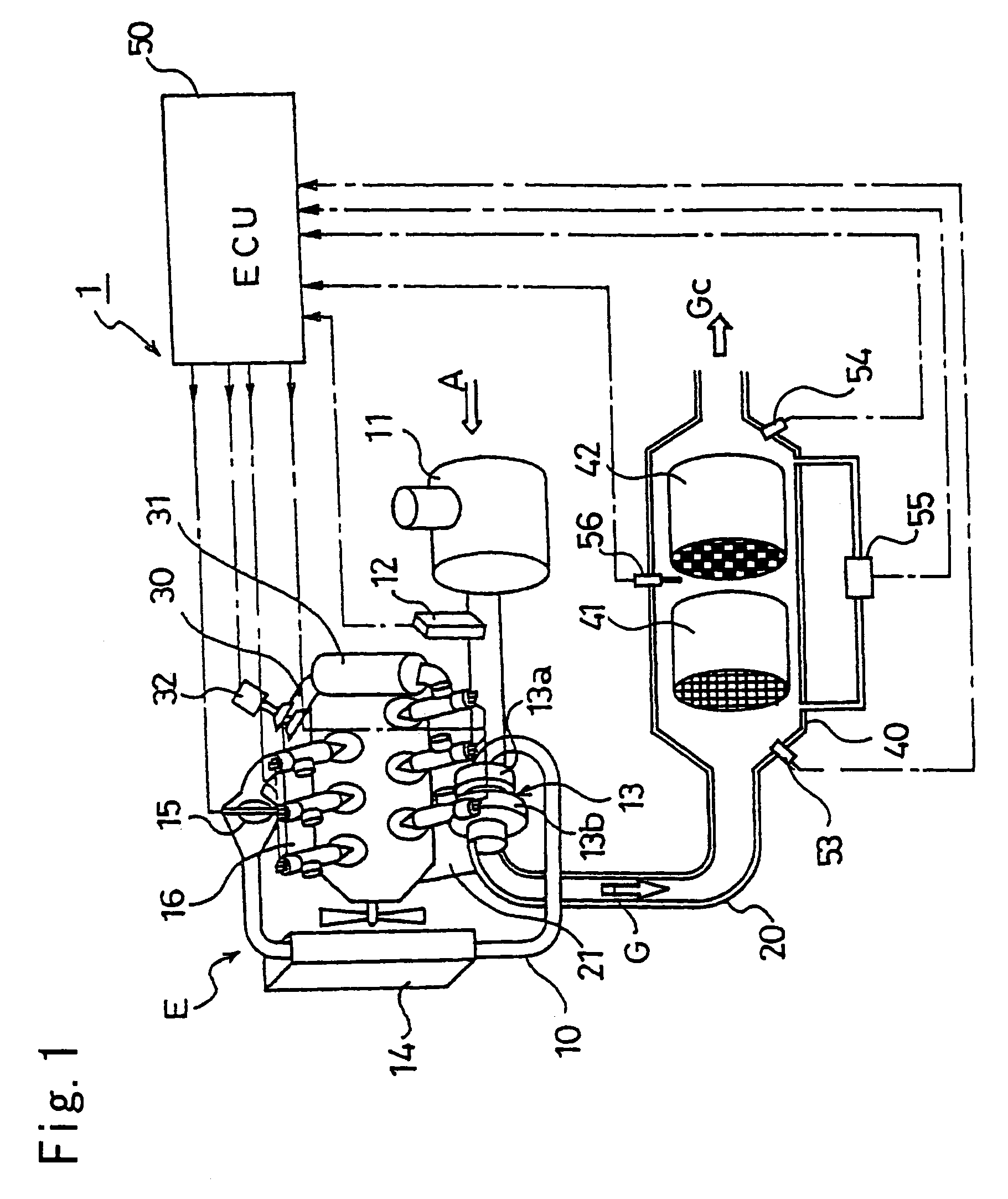
[0032]FIG. 1 shows the configuration of an exhaust gas purifying system 1 according to the present invention.

[0033]This exhaust gas purifying system 1 comprises an exhaust gas purifying device 40 having an upstream NOx occlusion reduction type catalyst 41 and a downstream DPF 42.

[0034]Furthermore, the NOx occlusion reduction type catalyst 41 is formed from a monolithic catalyst. In addition, a catalytic metal capable of oxidizing NOx and a NOx occluding material capable of occluding NOx are supported on the porous catalytic coating layer of alumina (Al2O3) and the like.

[0035]The porous catalytic coating layer comprises alumina (Al2O3) or the like, and the catalytic metal is formed of platinum (Pt) or the like. Furthermore, the NOx occluding material comprises an alkaline metal such as sodium (Na), potassium ...


PUM


Abstract

In an exhaust gas purifying system (b 1) that purifies NOx for the exhaust gas from an internal combustion engine (E) through sulfur purging control by a NOx occlusion reduction type catalyst (41), sulfur purging is judged to have started when the oxygen concentration (Co) detected by an oxygen concentration detector (54) disposed downstream of the NOx occlusion reduction type catalyst (41) drops from a first predetermined oxygen concentration indicating that the NOx discharge condition to a second predetermined oxygen concentration indicating that NOx discharge has ended and that Sox discharge has started. Accordingly, during sulfur purging control by the NOx occlusion reduction type catalyst (41), consideration is given to the discharge of NOx without sulfur purging at the start of sulfur purging control; furthermore, this timing is judged by monitoring the concentration of oxygen downstream of the NOx occlusion reduction type catalyst (41), thus optimizing sulfur purging control.

Description

BACKGROUND OF THE INVENTION[0001]The present invention relates to exhaust gas purifying methods and exhaust gas purifying systems aiming to optimize the start and stop timing of sulfur purging control for the resolution of sulfur poisoning of NOx occlusion reduction type catalysts.[0002]A wide range of research projects and proposals have dealt with the removing of particulate matter (PM) and nitrogen oxides (NOx) from the exhaust gasses generated by automobile internal combustion engines, mounted internal combustion engines, and the like, thus creating cleaner exhaust gasses. With regard to the purifying of NOx from exhaust gasses from automobiles and the like in particular, NOx occlusion reduction type catalysts, three way catalysts, and other NOx purifying catalysts are being used.[0003]These NOx occlusion reduction type catalysts are formed from monolithic catalysts and the like. Furthermore, these NOx occlusion reduction type catalysts are formed by providing a catalyst coat la...

Claims


Application Information

Patent Timeline
Patent Type & Authority Patents(United States)
IPC IPC(8): F01N3/00B01D53/94F01N3/035F01N3/08F01N3/20F01N13/02F02B29/04F02D41/02F02D41/14F02M25/07
CPCB01D53/9431B01D53/9495F01N3/035F01N3/0814F01N3/0821F01N13/0097F02D41/028F02D41/1475F01N2570/04F02B29/0406F02M25/0707F02M25/0727F01N2570/14F02M26/05F02M26/23Y02A50/20
Inventor NAGAOKA, DAIJIGABE, MASASHI
Owner ISUZU MOTORS LTD
Why Eureka
Try Eureka