Method and circuit arrangement for compensating for rate dependent change of conversion factor in a drift-type radiation detector and a detector appliance

a conversion factor and detector technology, applied in the direction of radiation intensity measurement, instruments, x/gamma/cosmic radiation measurement, etc., can solve the problem of difficult linearization circuit b>, circuit may be somewhat slow to react to changes in the photon hit rate, and the rate dependent shift in peak positions

Inactive Publication Date: 2007-03-20
OXFORD INSTR TECH OY
View PDF2 Cites 12 Cited by
  • Summary
  • Abstract
  • Description
  • Claims
  • Application Information

AI Technical Summary

Benefits of technology

[0011]An objective of the present invention is to compensate for the rate dependent change of charge-to-voltage conversion factor in a drift-type radiation detector. Especially an objective of the invention is to realize such compensation in a manner that is simple to implement and realiable in operation. Additionally an objective of the invention is to provide a detector appliance that is adapted to compensate for rate dependent shift of the peak positions resulting from said .

Problems solved by technology

A problem of conventional SDD-based detector appliances is the rate dependent shift in peak positions.
The circuit of FIG. 3 involves problems that mainly relate to its susceptibility to oscillations.
It may also prove to be difficult to realize the linearization circuit 307, because of the complexity of the nonlinear behaviour of the charge-to-voltage conversion factor.
The circuit may also be somewhat slow to react to changes in the photon hit rate.

Method used


Image

  • Method and circuit arrangement for compensating for rate dependent change of conversion factor in a drift-type radiation detector and a detector appliance
  • Method and circuit arrangement for compensating for rate dependent change of conversion factor in a drift-type radiation detector and a detector appliance
  • Method and circuit arrangement for compensating for rate dependent change of conversion factor in a drift-type radiation detector and a detector appliance

Examples


Embodiment Construction

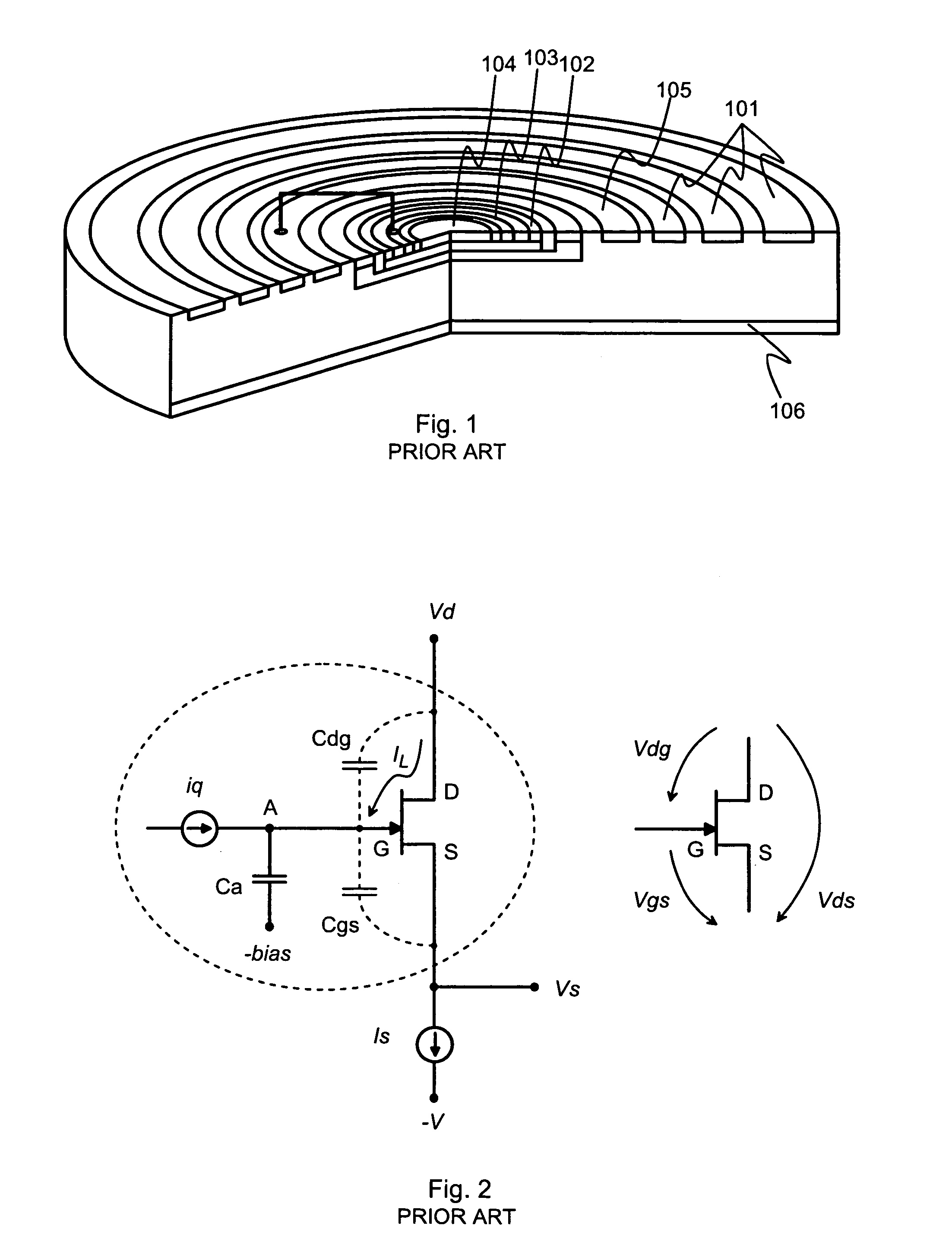
[0037]From the scientific publication of E. Elad mentioned above we may draw an expression for the leakage current IL:

[0038]IL=Id·α·Vds·ⅇ-βVds(3)

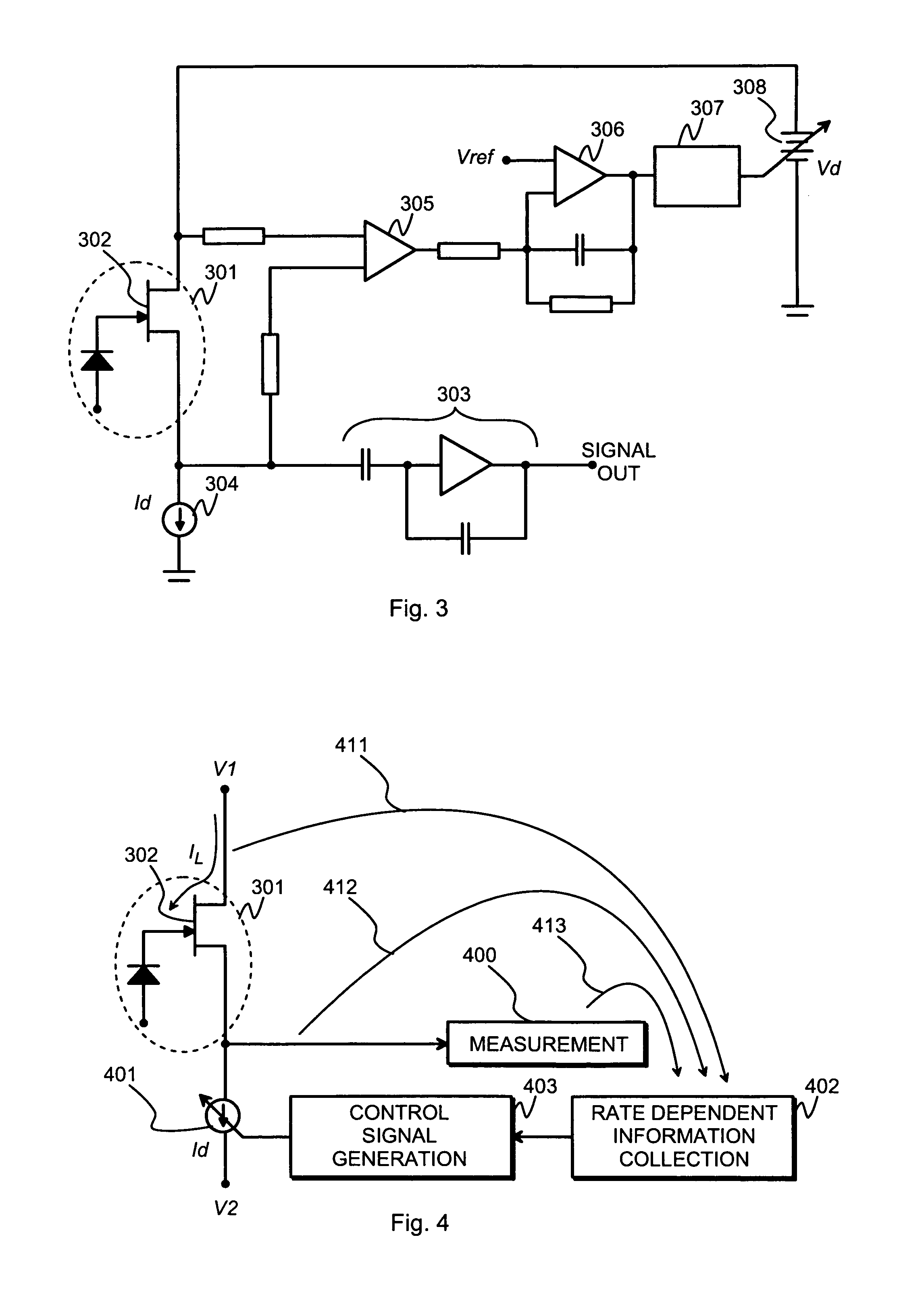
where α and β are material—and temperature dependent constants. This expression is illustrative in two ways. Firstly, it confirms the statement made above about the complicated nonlinear relationship between IL and Vds, which makes it difficult to achieve satisfactory results by tampering with the value of Vds, which we attempted in FIG. 3. Secondly expression (3) shows that the dependency between IL and Id is much simpler, even linear. We may thus deduce that it is possible to compensate for a purely rate dependent distortion of IL by causing a comparable distortion to Id, so that as a result Vds assumes the value it would have without said rate dependent distortion of IL.

[0039]FIG. 4 illustrates schematically an arrangement in which a drift type detector chip 301 is used for detecting radiation. A FET 302 on the drift type detector chip 3...


PUM


Abstract

For compensating for the rate dependent change of charge-to-voltage conversion factor in a drift-type radiation detector there is detected a change in a momentary photon hit rate affecting said drift-type radiation detector. A drain current flowing through an integrated amplifier of said drift-type radiation detector is changed by an amount proportional to the detected change in said momentary photon hit rate.

Description

TECHNICAL FIELD[0001]The invention concerns generally the technology of solid-state detectors for electromagnetic radiation. Especially the invention concerns a way of compensating for the shifting of peak positions as a rate of photon count rate in a drift-type detector used e.g. to detect X-rays.BACKGROUND OF THE INVENTION[0002]A traditional solid-state detector type to be used for X-ray detection in e.g. imaging and spectroscopy applications is the PIN detector. There the detecting element is a reverse biased PIN diode, one electrode of which is coupled to the gate of a FET (field-effect transistor). X-ray photons that hit the PIN diode cause a photoelectric effect, creating a number of free electrons and holes in a depleted region formed in the semiconductor material. The bias voltage across the PIN diode causes the mobile charge carriers to be drawn to the electrodes, which changes electrode potential. An integrator coupled to the FET transforms the change of the PIN diode's el...

Claims


Application Information

Patent Timeline
Patent Type & Authority Patents(United States)
IPC IPC(8): G01T1/24
CPCH03F3/087H03F3/082
Inventor KIURU, ERKKI SAKARI
Owner OXFORD INSTR TECH OY
Why Eureka
Try Eureka