Voltage regulator

a voltage regulator and voltage regulator technology, applied in the direction of process and machine control, packaging, instruments, etc., can solve the problems of not thoroughly reducing consumption current, current consumption occurring on the reference voltage circuit b>1/b> and the operational amplifier, and achieve the effect of reducing consumption curren

Active Publication Date: 2007-03-20
LAPIS SEMICON CO LTD
View PDF5 Cites 62 Cited by
  • Summary
  • Abstract
  • Description
  • Claims
  • Application Information

AI Technical Summary

Benefits of technology

[0010]It is an object of the present invention to reduce the current consumption for a voltage regulator in sleep mode.
[0012]The voltage regulator according to the invention has the reference voltage circuit and amplifier circuit that ceases operation in sleep mode, and a sub-regulator circuit that, in sleep mode, generates the lower power voltage different from the internal power voltage and supplies same to the output terminal. This provides an effect that the consumption current can be reduced in sleep mode.

Problems solved by technology

However, in the voltage regulator circuit, current consumption occurs on the reference voltage circuit 1 and operational amplifier 2 also when no load current flows.
Thus, there is a problem that consumption current is not reduced thoroughly.

Method used


Image

  • Voltage regulator
  • Voltage regulator
  • Voltage regulator

Examples


first embodiment

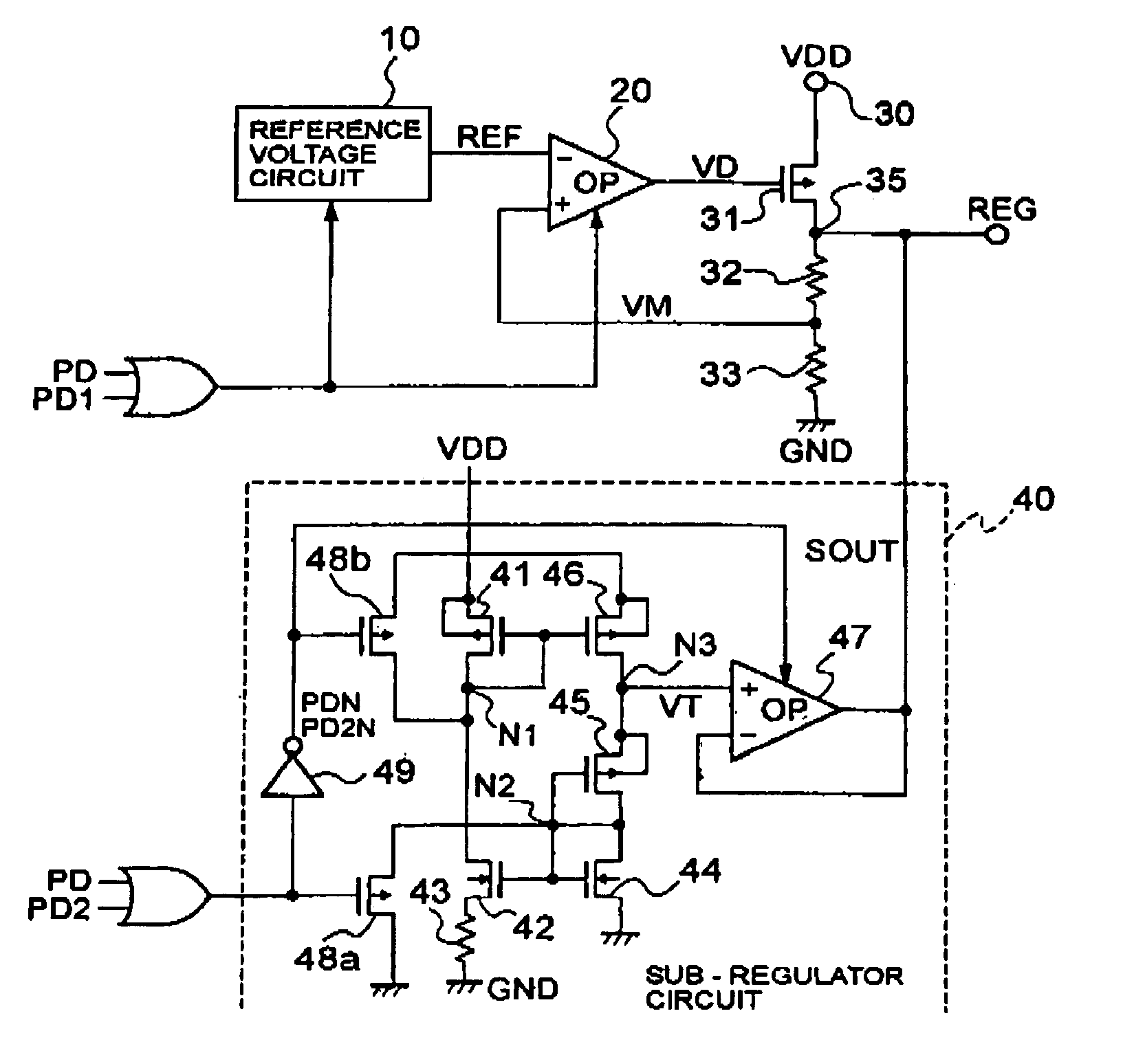
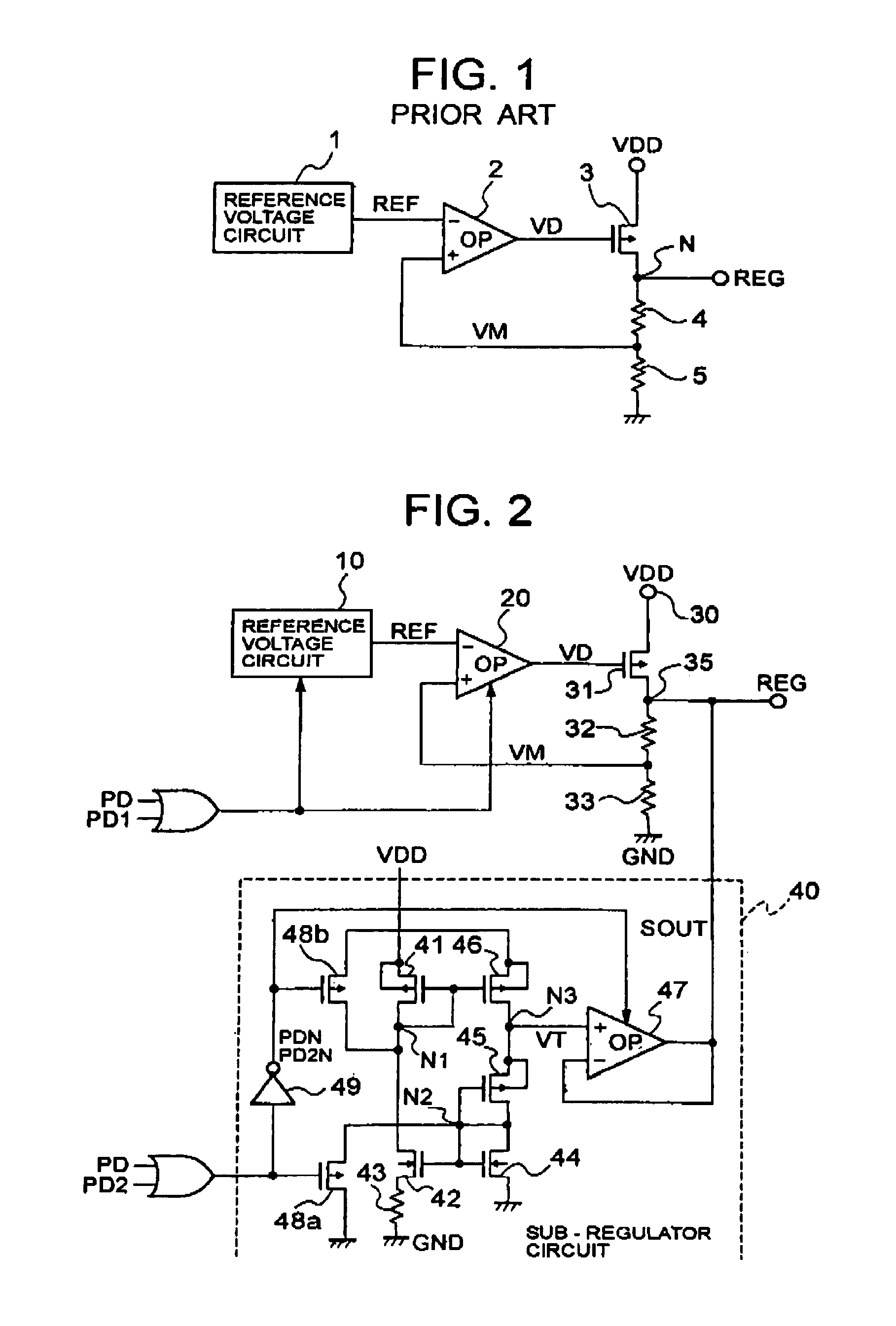
[0023]FIG. 2 is a configuration diagram of a voltage regulator showing the present invention.

[0024]The voltage regulator is for regulating an externally supplied power-source voltage VDD and outputting a constant internal power voltage REG, which includes a reference voltage circuit 10 having a power-down function and an operational amplifier 20. The reference voltage circuit 10 generates a reference voltage REF based on a band gap or the like. For example, a switch element such as an N-channel MOS transistor (hereinafter referred to as “NMOS”) is inserted intermediately to the ground voltage GND and placed under control according to power-down signals PD, PD1, the reference voltage circuit 10 can be cut off from the ground voltage GND and ceased from operating during sleep mode. Likewise, the operational amplifier 20 are also cut off from the ground voltage GND according to the power-down signals PD, PD1, and ceased from operating in sleep mode. Here, the power-down signal PD is to...

second embodiment

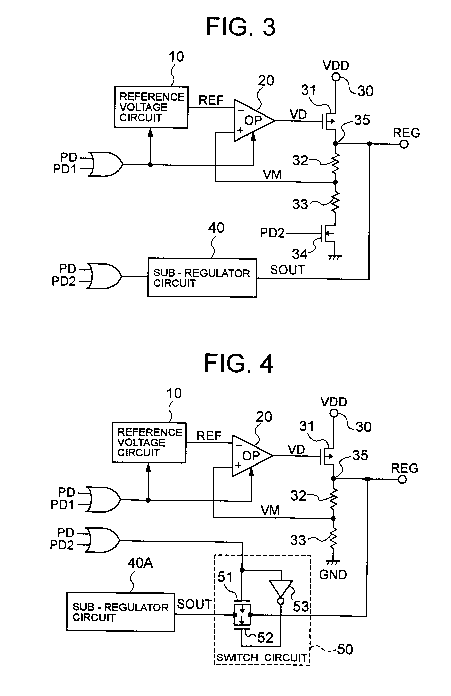
[0044]FIG. 3 is a configuration diagram of a voltage regulator showing a second embodiment in the invention, wherein the common element to that of FIG. 1 is attached with the common reference.

[0045]The voltage regulator is configured with a switch NMOS 34 inserted, in the FIG. 2 voltage regulator, in series between the voltage-dividing circuit based on the resistances 32, 33 and the ground voltage GND so that the NMOS 34 can be controlled on-off according to a power-down signal PD1 common to the reference voltage circuit 10 and operational amplifier 20. The others are similar in structure to those of FIG. 2.

[0046]The voltage regulator, in normal operation mode, operates similarly to that of FIG. 2 because the NMOS 34 is turned on according to the power-down signal PD2 in “H”. Although the monitor voltage VM is somewhat changed by the addition of an NMOS 34 on-resistance to the resistance 33, the change is extremely small as compared to the value of the resistance 32, 33 and hence sl...

third embodiment

[0049]FIG. 4 is a configuration diagram of a voltage regulator showing a third embodiment in the invention, wherein like reference numerals are used to denote the elements shown in FIG. 2.

[0050]In the voltage regulator, a sub-regulator circuit 40A somewhat simplified in configuration is provided in place of the sub-regulator circuit 40 of the FIG. 2 voltage regulator, wherein the output of the sub-regulator circuit 40A is connected to the output terminal 35 through a switch circuit 50.

[0051]The sub-regulator circuit 40A is a version of the FIG. 2 sub-regulator circuit 40 omitted of the power-down control circuit, i.e. NMOS 48a, PMOS 48b and inverter 49, and the operational amplifier 47 omitted of the power-down function. The switch circuit 50, so-called a transfer gate, is configured with a parallel connection of a PMOS 51 and an NMOS 52, in a manner to supply a logical sum of power-down signals PD, PD2 to a gate of the PMOS 51 and an inverted logical sum, by an inverter 53, of powe...


PUM


Abstract

Consumption current is reduced for a voltage regulator in sleep mode. In normal operation mode, a sub-regulator circuit is ceased from operating according to a power-down signal, which allows an operation amplifier to compare between a reference voltage outputted from a reference voltage circuit and a monitor voltage generated by a voltage-dividing circuit. Based on a detection voltage as a comparison result, a PMOS is controlled to regulate an internal power voltage such that the monitor voltage becomes equal to the reference voltage. In sleep mode, the reference voltage circuit and operational amplifier is ceased from operating, to start up the sub-regulator circuit. A slight current, restricted by a resistance, flows through a PMOS of the sub-regulator circuit. The same magnitude of current is supplied from the PMOS constituting a current mirror to a PMOS, etc. of a threshold-voltage output circuit. The threshold voltage, at a node between the PMOS constituting the current mirror and the PMOS of the threshold-voltage output circuit, is power-amplified by a voltage follower and outputted through an output terminal.

Description

BACKGROUND OF THE INVENTION[0001]1. Field of the Invention[0002]The present invention relates to a voltage regulator that is to output a constant voltage regardless of the variations in power voltage supplied or load current outputted, and more particularly to the reduction of current consumption in the power save mode thereof.[0003]2. Description of the Related Art[0004]FIG. 1 is a configuration diagram of an existing voltage regulator.[0005]The voltage regulator is configured with a reference voltage circuit 1 that generates a reference voltage REF based on a band gap, etc., an operational amplifier (OP) 2 that compares the reference voltage REF with a monitor voltage VM and outputs a detection voltage VD according to the difference thereof, a P-channel MOS transistor (hereinafter, referred to as “PMOS”) 3 connected between a power voltage VDD externally supplied and an output node N outputting a constant internal power voltage REG, in a manner controlled in conduction by a detect...

Claims


Application Information

Patent Timeline
Patent Type & Authority Patents(United States)
IPC IPC(8): G05F1/40
CPCG05F1/565A47G19/24B65D81/3261
Inventor AIKAWA, AKIYOSHI
Owner LAPIS SEMICON CO LTD
Why Eureka
Try Eureka