Scheme for determining internal mode using MCLK frequency autodetect

a technology of autodetect and internal mode, applied in the direction of digital-analog converters, instruments, digital recording/recording, etc., can solve the problems of increasing complexity and capability of conventional data converters, requiring precise timing, and requiring precise timing, so as to achieve the effect of not adding excessive overhead

Active Publication Date: 2007-03-20
CIRRUS LOGIC INC
View PDF6 Cites 7 Cited by
  • Summary
  • Abstract
  • Description
  • Claims
  • Application Information

AI Technical Summary

Benefits of technology

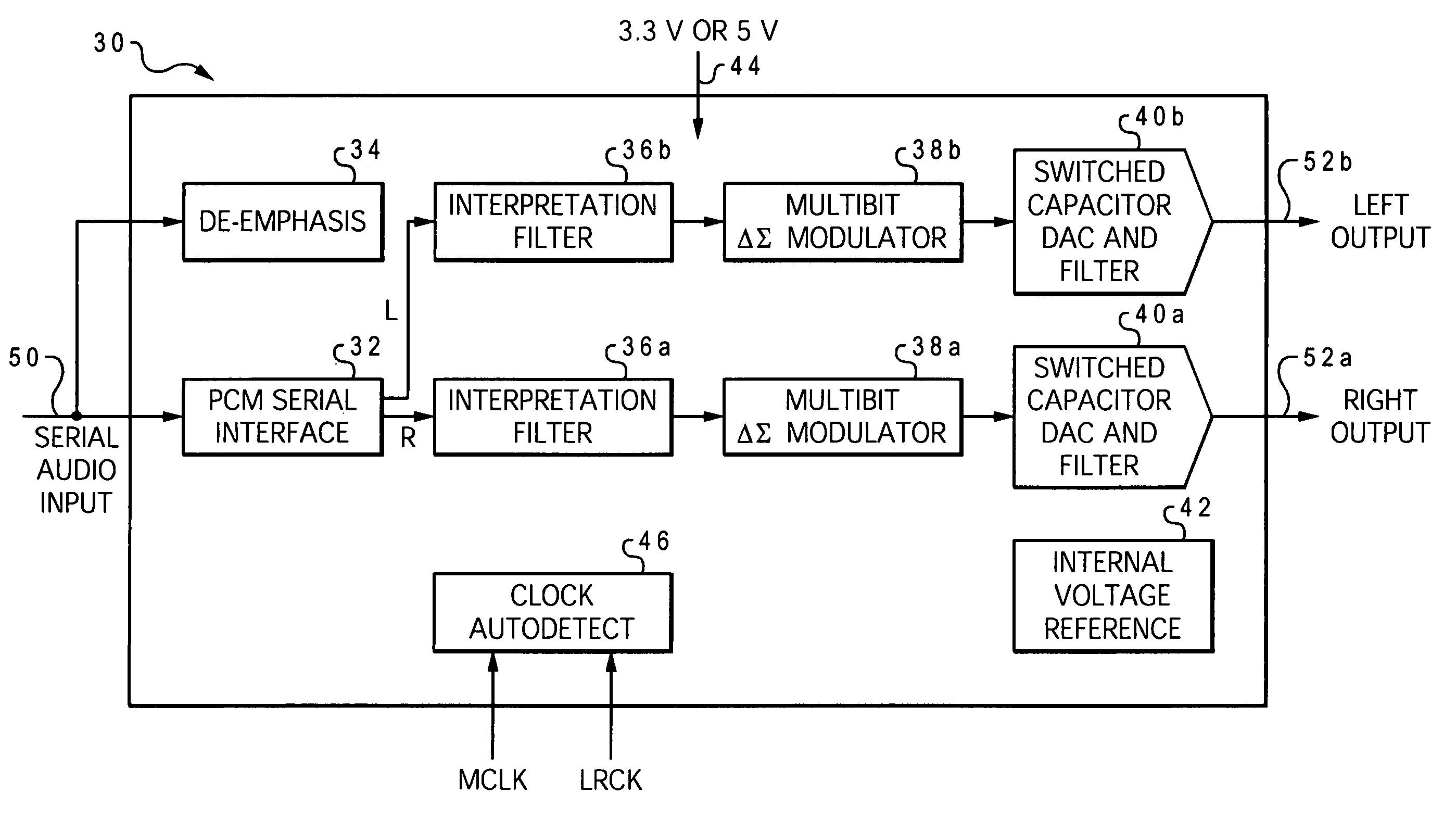
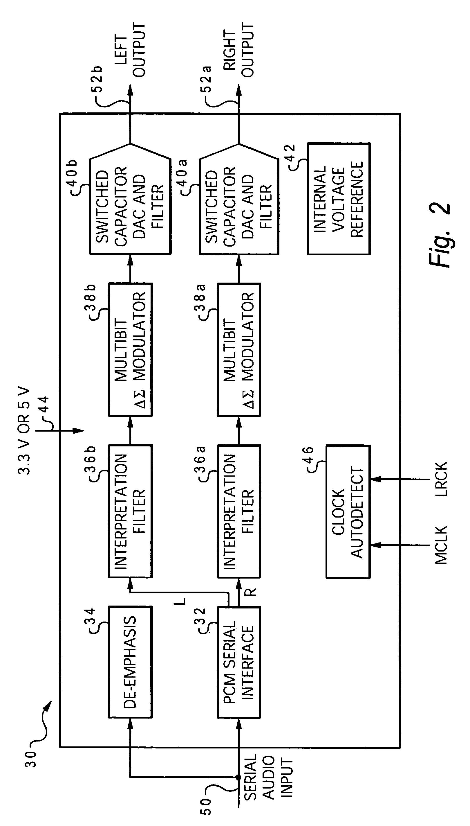
[0015]The present invention provides a digital-to-analog converter that can automatically detect which operating mode is to be used based on exte

Problems solved by technology

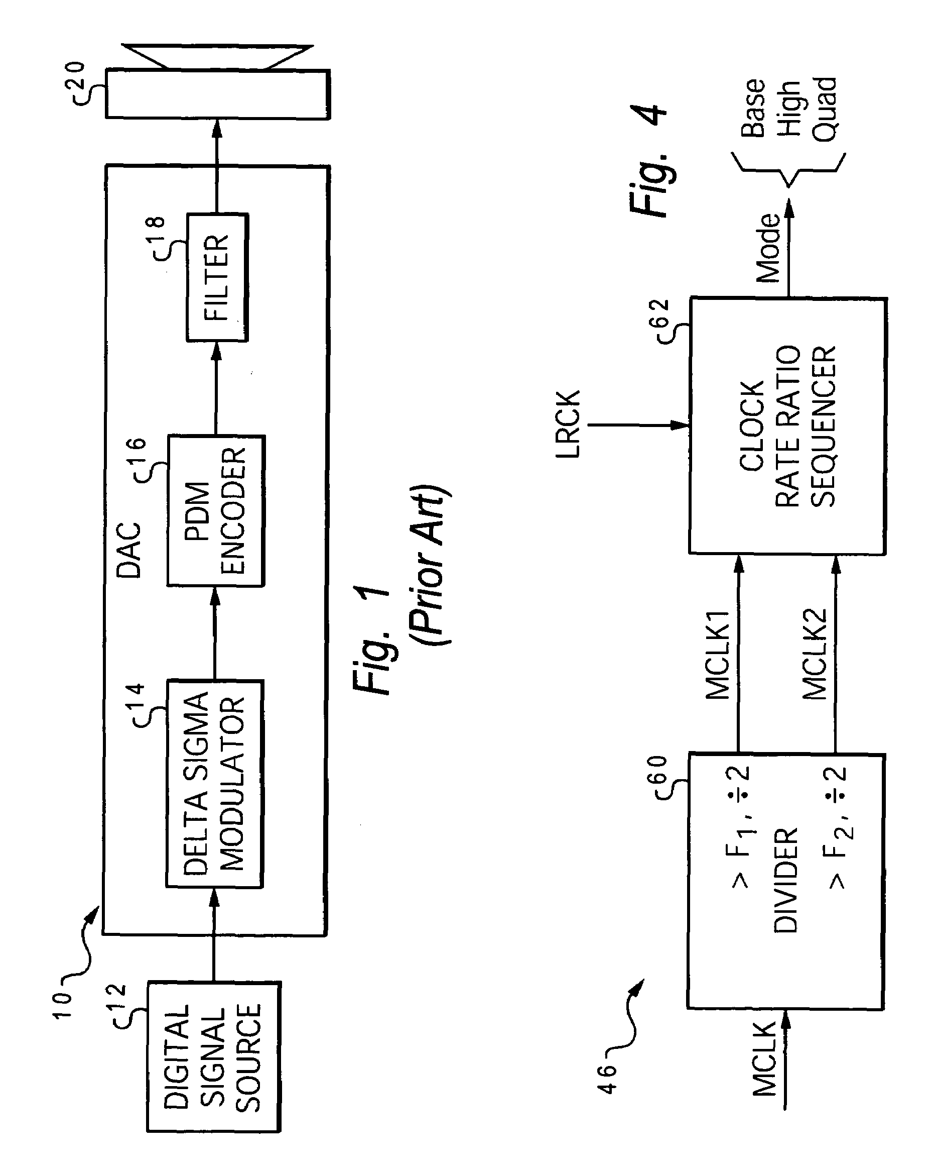
Conventional data converters have dramatically grown in complexity and capability, and their clocking systems have also grown in complexity to more fully utilize the function and high performance provided by CMOS technology.
However, this scheme requires precise timing.
Clock design becomes further complicated when a DAC must support a variety of external clock inputs.
Unfortunately, existing solutions for establishing the pro

Method used


Image

  • Scheme for determining internal mode using MCLK frequency autodetect
  • Scheme for determining internal mode using MCLK frequency autodetect
  • Scheme for determining internal mode using MCLK frequency autodetect

Examples


example 1

[0053]MCLK is 18 MHz, LRCK is 48 kHz, and it is assumed that the first trip frequency is close to (or below) its nominal rate of 16 MHz. MCLK will accordingly trip F1 but not trip F2. Therefore:

[0054]MCLK1=9 MHz

[0055]MCLK2=18 MHz

[0056]ratio for first mux input=9 MHz / 48 kHz=192

[0057]ratio for second mux input=12 MHz / 48 kHz=256

[0058]ratio for third mux input=4.5 MHz / 48 kHz=96

[0059]ratio for fourth mux input=8 MHz / 48 kHz=167

Result: 256 is identified as a valid ratio during the first check cycle, and the base mode of operation is enabled.

example 2

[0060]Similar to Example 1, MCLK is 18 MHz and LRCK is 48 kHz, but it is now assumed that the first trip frequency is greatly above its nominal rate (i.e., it is above 18 MHz). MCLK will accordingly not trip either F1 or F2. Therefore:

[0061]MCLK1=18 MHz

[0062]MCLK2=18 MHz

[0063]ratio for first mux input=18 MHz / 48 kHz=384

[0064]ratio for second mux input=12 MHz / 48 kHz=256

[0065]ratio for third mux input=9 MHz / 48 kHz=192

[0066]ratio for fourth mux input=8 MHz / 48 kHz=167

Result: 256 is still identified as a valid ratio during the first check cycle, and the base mode of operation is enabled.

example 3

[0067]MCLK is 18 MHz, LRCK is 192 kHz, and it is again assumed that the first trip frequency is close to (or below) its nominal rate of 16 MHz. MCLK will accordingly trip F1 but not trip F2. Therefore:

[0068]MCLK1=9 MHz

[0069]MCLK2=18 MHz

[0070]ratio for first mux input=9 MHz / 192 kHz=48

[0071]ratio for second mux input=12 MHz / 192 kHz=64

[0072]ratio for third mux input=4.5 MHz / 192 kHz=24

[0073]ratio for fourth mux input=8 MHz / 192 kHz=43

Result: 64 is identified as a valid ratio during the third check cycle, and the quad mode of operation is enabled.

[0074]The clock autodetect feature of the present invention may be further understood with reference to the flow chart of FIG. 7. The process starts at power up block 90. The autodetect unit waits until both an MCLK and an LRCK are detected at block 92. The MCLK rate is then compared to the first trip frequency at decision block 94. If MCLK is less than or equal to F1, then MCLK1 is set to MCLK at block 96, but if MCLK is greater than F1, then MC...


PUM


Abstract

A method of determining an internal operating mode of an electronic circuit derives multiple comparison rates from a rate of a master clock input, computes one or more clock ratios of the comparison rates to a rate of a sample rate clock input, and determines whether any of the clock ratios is a valid ratio representing a supported clock configuration. The appropriate internal operating mode is then selected based on the valid ratio. In the illustrative embodiment, a clock autodetect unit uses two trip frequencies to derive at least first and second clock comparison rates. The audio converter can operate in three distinct modes (base, high and quad modes). The base mode is selected when the clock ratio is about 256, the high mode is selected when the clock ratio is about 128, and the quad mode is selected when the clock ratio is about 64. A multiplexer can be used to sequence through the computer clock ratios to ensure that a highest valid ratio is used among a plurality of valid ratios.

Description

CROSS-REFERENCE TO RELATED APPLICATION[0001]This application claims priority from U.S. Provisional Patent Application No. 60 / 574,330, entitled “CLOCK MODE DETECTION SCHEMES IN DATA CONVERTERS” filed May 25, 2004, which is hereby incorporated.BACKGROUND OF THE INVENTION[0002]1. Field of the Invention[0003]The present invention generally relates to clocking systems for electronic circuits, and more particularly to a method of determining which of a plurality of different operating modes is to be used by a circuit, which is adapted to receive a variety of external clock signals.[0004]2. Description of the Related Art[0005]Various types of electronic circuits have been constructed that support a wide range of different clock modes. For example, data converters can operate in different speed modes in which different master clock rates and sample clock rates are used. A digital-to-analog converter might have two operating modes, such as a base mode and a high mode, depending on what maste...

Claims


Application Information

Patent Timeline
IPC IPC(8): H03M1/66
CPCH03M3/50G11B20/10G11B20/14
Inventor NANDA, KARTIKRANGAN, GIRIAMAR, ARYESH
Owner CIRRUS LOGIC INC
Why Eureka
Try Eureka