Dual liquid crystal display device

a liquid crystal display and dual technology, applied in the field of dual liquid crystal display devices, can solve the problems of reducing the display area is not effective in the aspect of utilization, and the manufacturing cost is elevated compared to the transmission type lcd device that displays images, so as to reduce the transmission mode light loss, simplify the structure of the lcd panel, and reduce the effect of light loss

Inactive Publication Date: 2007-03-20
SAMSUNG DISPLAY CO LTD
View PDF13 Cites 17 Cited by
  • Summary
  • Abstract
  • Description
  • Claims
  • Application Information

AI Technical Summary

Benefits of technology

[0018]Accordingly, the present invention is to solve the aforementioned and other problems of the conventional art, and it is an object of the present invention to provide an LCD device capable of simplifying a structure of an LCD panel, decreasing light loss in the transmission mode and performing a bi-directional image display.
[0021]In an exemplary embodiment, the LCD device includes a first transflective film disposed at one of the first and second display units. The first transflective film has a plurality of layers in which a first layer and a second layer having different refractivity indexes from each other are alternately stacked, so that the first transflective film partially reflects and partially transmits a first incident light incident on the first transflective film. The LCD device includes a light supplying unit disposed between the first and second display units. The light supplying unit controls an amount of the light that is provided to the first and second display units, to thereby regulate a contrast ratio of a luminance between the first and second display units. Therefore, the structure of an LCD panel for performing a bi-directional image display can be simplified, and the light loss in the transmission mode can be reduced.
[0022]In another exemplary embodiment, the LCD device includes an anisotropy transflective film or an isotropy transflective film disposed at one of the first and second display units. The anisotropy transflective film has an optical characteristic in which light components in a specific direction are strongly reflected and polarization components in a direction perpendicular to the specific direction are partially transmitted and reflected depending on polarized state and direction of the incident light incident thereto. The isotropy transflective film has an optical characteristic in which light components are partially transmitted and reflected independent of polarized state and direction of the incident light. As a result, by a light restoring process occurring between the transflective film and the backlight, the restored light is transmitted through the transflective film repeatedly, so that transmissivity and light efficiency can be enhanced.
[0023]Further, the LCD device has no reflection electrode within liquid crystal (LC) cell and has no ¼-wavelength phase difference plate on each of the first substrate and the second substrate. Accordingly, compared with a conventional LCD device, the LCD device of the present invention can be made in more simple structure, and degeneration in the reliability of the liquid crystal can be prevented.
[0024]Furthermore, since the light supplying unit disposed between the first and second display units regulates the luminance of the light generated from the lamp to provide the first and second display units with the light of which luminance is regulated, the LCD device of the present invention satisfies the demand from users.

Problems solved by technology

First, since a display area of the LCD device is divided into a transmission area used in the transmission mode and a reflection area used in the reflection mode, it is not effective in aspect of utilization of the display area.
Second, since the conventional LCD device has to employ the wide band ¼ wavelength phase difference plates covering an overall frequency band of the visible ray, as well as a first and a second polarizing plates attached on each of the first and second substrates, a manufacturing cost is elevated compared with a transmission type LCD device that displays images by means of a backlight disposed under the LCD panel.
Third, since the polarization characteristic in the transmission mode causes a light loss of 50%, there are drawbacks in that a light transmissivity decreases by 50% and a contrast ratio (C / R) is lowered.
Fourth, since Δnd (Δn: a value for representing optical anisotropy or refractive anisotropy; d: cell gap) of a liquid crystal layer is only 0.24 μm which is a half of Δnd (0.48 μm) of the conventional transmission type LCD device, the cell gap of the liquid crystal cell should be decreased to a level of 3 μm, and the Δn of the liquid crystal also should be decreased. Accordingly, there are problems in that the manufacturing process becomes difficult and degeneration in the reliability of the liquid crystal is caused.

Method used


Image

  • Dual liquid crystal display device
  • Dual liquid crystal display device
  • Dual liquid crystal display device

Examples


Embodiment Construction

[0042]Now, exemplary embodiments of the present invention will be described in detail with reference to the annexed drawings.

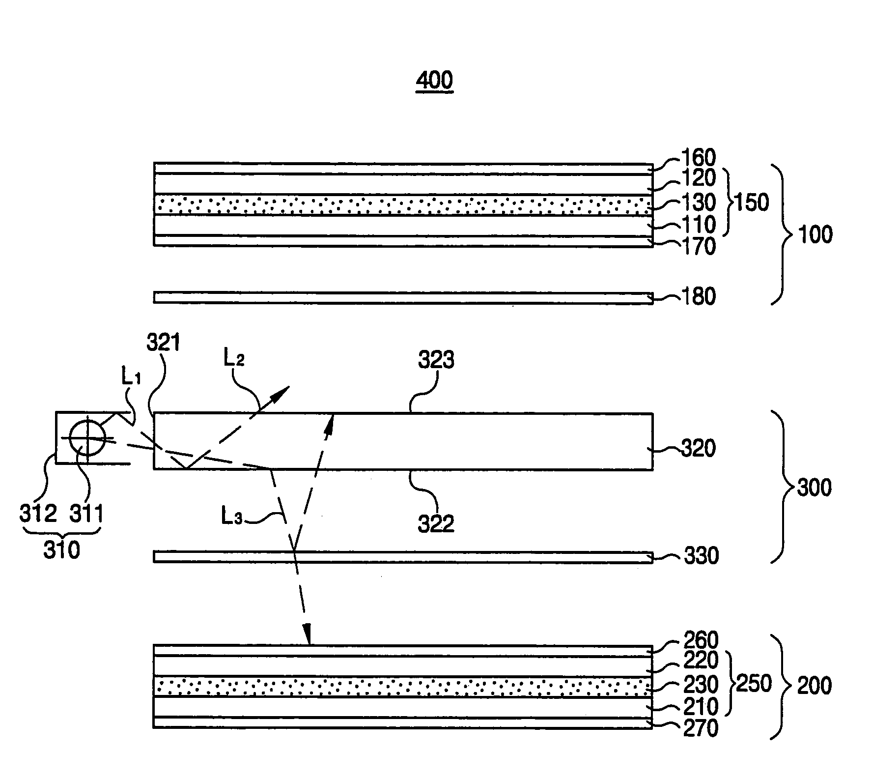
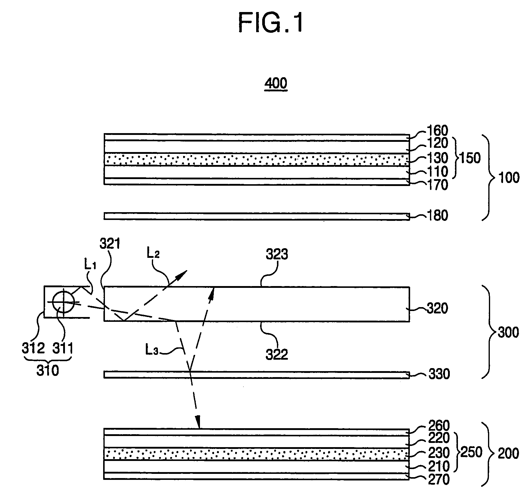
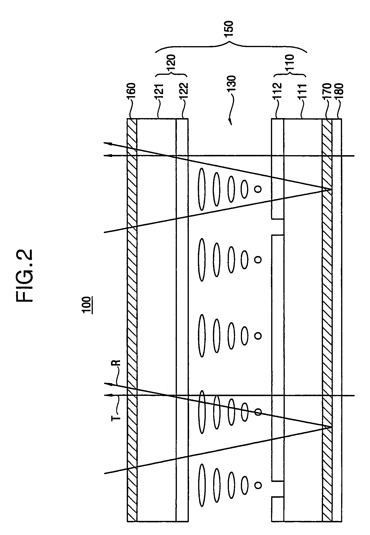
[0043]FIG. 1 is a sectional view showing a liquid crystal display device according to an exemplary embodiment of the present invention, and FIG. 2 is a sectional view showing a first display unit of FIG. 1.

[0044]Referring to FIG. 1, an LCD device includes a first display unit 100 for displaying first images, a second display unit 200 for displaying second images, and a light supplying unit (Hereinafter, refer to a backlight) 300 disposed between the first and the second display units 100, 200.

[0045]The first display unit 100 includes a first LCD panel 150, a first polarizing plate 160, a second polarizing plate 170 and a transflective film 180. The first LCD panel 150 includes a first substrate 110, a second substrate 120 of which an lower surface is arranged facing the first substrate 110, and a first liquid crystal layer 130 disposed between the first substr...


PUM

PropertyMeasurementUnit
thicknessaaaaaaaaaa
reflectivityaaaaaaaaaa
luminanceaaaaaaaaaa

Abstract

Disclosed is an LCD device for performing bi-directional display. The LCD device includes first and second display units, and a light supplying unit. The first display unit includes an LCD panel and a transflective film that is disposed under the LCD panel and has layers in which first and second layers having different refractivity indexes are alternately stacked. The transflective film partially reflects and transmits light incident onto the film. The light supplying unit is disposed between the first and second display units, and provide the first and second display units with light generated from a lamp by dividing the light, to thereby regulate a contrast ratio of a luminance between the first and second display units. Therefore, the structure of an LCD panel for performing bi-directional image display can be simplified, and the light loss in the transmission mode can be reduced.

Description

CROSS-REFERENCE TO RELATED APPLICATIONS[0001]The present application is a continuation of the earlier filed non-provisional application, having U.S. application Ser. No. 10 / 454,700, filed on Jun. 3, 2003 now U.S. Pat. No. 6,831,711, which is incorporated herein in its entirety.BACKGROUND OF THE INVENTION[0002]1. Field of the Invention[0003]The present invention relates to a liquid crystal display (LCD) device, and more particularly to a liquid crystal display device in which a light loss of the liquid crystal display device is reduced in a transmission mode and a bi-directional display is provided.[0004]2. Description of the Related Art[0005]In these days, electronic display devices become more important for communicating and processing various information. Also, various types of electronic display devices are widely used in different industrial fields.[0006]Generally, an electronic display device visually provides a variety of information to a user. In other words, an electrical in...

Claims


Application Information

Patent Timeline
Patent Type & Authority Patents(United States)
IPC IPC(8): G02F1/1347G02B5/30G02F1/1333G02F1/1335G02F1/13357G02F1/13363
CPCG02B5/3083G02F1/133605G02F1/133615G02B6/0063G02B6/0043G02B6/0061G02F2001/133342G02F1/133342G02F1/133507G02F1/1347
Inventor CHOI, JUNG-MINLEE, DONG-HO
Owner SAMSUNG DISPLAY CO LTD
Why Eureka
Try Eureka