
Nozzle-based, vapor-phase, plume delivery structure for use in production of thin-film deposition layer

a technology of nozzles and thin films, applied in the direction of sustainable manufacturing/processing, final product manufacturing, separation processes, etc., can solve the problems of high cost of sputtering systems, poor utilization of source (target) resources, and limited time for creating multi-component films

Inactive Publication Date: 2007-03-20
UD TECH CORP +2
View PDF18 Cites 307 Cited by
  • Summary
  • Abstract
  • Description
  • Claims
  • Application Information

AI Technical Summary

Problems solved by technology

Negative aspects of sputtering including the high cost of the sputtering systems, that the source (target) utilization is generally poor (20 to 40%), and that there are temporal limitations in creating multi-component films (i.e., more that three elements).
More specifically, to sputter multi-component films, individual layers are usually deposited followed by a heat treatment cycle to react the components together, which may require considerable time.
However, to achieve a uniform film thickness using evaporation requires multiple evaporation sources.
However, application of evaporation to complex multi-component films that contain one or more highly reactive species has proved problematic due to the relative consistent rate control and thickness uniformity issues.
As noted above, complex multi-element films are difficult to produce using currently available techniques of sputtering or evaporation.
As a standalone device, conventional solar cells do not have a sufficient voltage required to power most applications.
Although commercial use and interest in thin-film photovoltaics has increased dramatically over the past five years, commercial wide-scale use of thin film PVs for bulk power generation historically has been limited due to PV's low performance and high cost.

Method used


Image

  • Nozzle-based, vapor-phase, plume delivery structure for use in production of thin-film deposition layer
  • Nozzle-based, vapor-phase, plume delivery structure for use in production of thin-film deposition layer
  • Nozzle-based, vapor-phase, plume delivery structure for use in production of thin-film deposition layer

Examples


Embodiment Construction

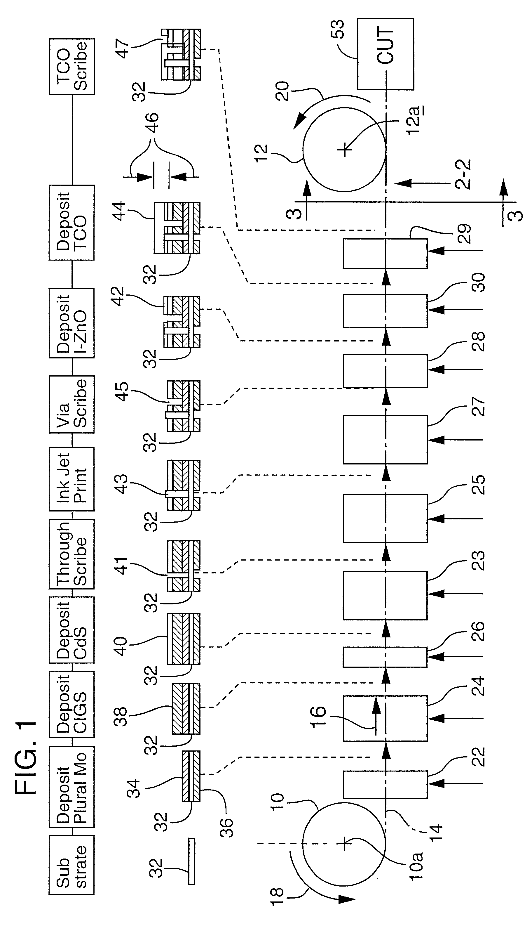
[0052]FIG. 1 illustrates the steps involved preferably in making a new kind of photovoltaic (PV) module in a roll-to-roll, continuous-motion process in accordance with the present invention. Those skilled in the art should understand that, while roll-to-roll, continuous motion processing is employed in the described embodiment, non-roll-to-roll procedures could be used effectively in certain applications.

[0053]FIG. 1 shows two rolls 10, 12, at the left and right, respectively, which symbolize the several roll-to-roll, continuous-motion processing stages employed in the manufacturing of this new kind of PV module. Roll 10 represents a pay-out roll, and roll 12, a take-up roll. It should be understood that rolls 10, 12 are representative of the different pay-out and take-up rolls that are employed in different isolated processing chambers. Thus, there are typically multiple pay-out and take-up rolls used during the overall process.

[0054]A stretched-out, flat portion of an elongate str...


PUM

PropertyMeasurementUnit
diameteraaaaaaaaaa
diameteraaaaaaaaaa
areaaaaaaaaaaa

Abstract

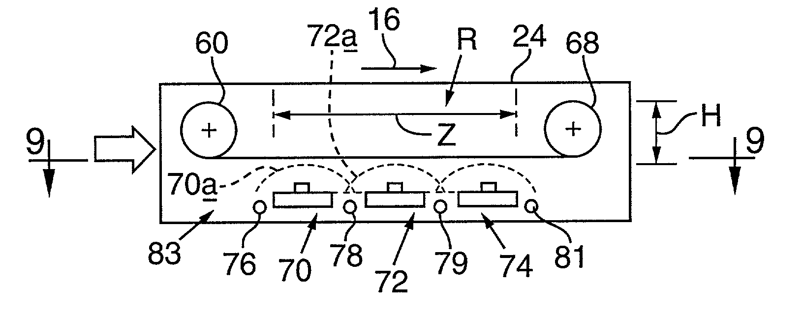
A vapor deposition source including a crucible configured to hold a quantity of molten constituent material and at least one nozzle to pass vapor evaporated from the molten constituent material out of the crucible.

Description

CROSS REFERENCE TO RELATED APPLICATIONS[0001]This application is a continuation of U.S. patent application Ser. No. 09 / 527,542 filed Mar. 16, 2000 now U.S. Pat. No. 6,310,281 titled “Thin-Film, Flexible Photovoltaic Module” and U.S. patent application Ser. No. 09 / 527,316 filed Mar. 16, 2000 now U.S. Pat. No. 6,372,538 titled “Thin-Film, Flexible Photovoltaic Module”, both of which are hereby incorporated by reference.[0002]This invention was made with Government support under Agreement No. MDA972-95-3-0036 awarded by DARPA. The Government has certain rights in the invention.TECHNICAL FIELD, BACKGROUND ART AND TECHNICAL ISSUES, SUMMARY OF THE INVENTION[0003]1. Field of the Invention[0004]The invention disclosed herein relates to the field of thin-film deposition, in general to controlled evaporation of single component elements to create complex multi-element films.[0005]2. Background of the Invention[0006]Looking briefly at the background of the invention, thin-film deposition is ty...

Claims


Application Information

Patent Timeline
Patent Type & Authority Patents(United States)
IPC IPC(8): C23C14/00C23C10/54
CPCC23C14/0021C23C14/0623C23C14/24C23C14/243C23C14/548H01L31/0749C23C14/562Y02E10/541H01L21/02554H01L21/02568H01L21/02631Y02P70/50
Inventor WENDT, ROBERT G.WIEDEMAN, SCOTTBRITT, JEFFREY S.MASON, DOUGLAS G.
Owner UD TECH CORP
Learn More