Screen for fiberizing bushings and method

a technology of fiberizing bushings and fibers, which is applied in the direction of lighting and heating equipment, manufacturing tools, furniture, etc., can solve the problems of not being able to meet the needs of non-channel positions, the temperature profile of the tip plate is greatly improved, and the efficiency of the tip plate is greatly improved. , to achieve the effect of reducing the variation of the fiber diameter of the fiber, and improving the temperature profile of the tip pla

Inactive Publication Date: 2007-03-27
JOHNS MANVILLE INT INC
View PDF10 Cites 3 Cited by
  • Summary
  • Abstract
  • Description
  • Claims
  • Application Information

AI Technical Summary

Benefits of technology

[0007]It has been discovered that if the hole density, number of holes per unit area, and / or the hole diameter, is decreased in the screen in the area above where the hotter glass flow negatively affects the tip plate temperature profile, the temperature profile of the tip plate is greatly improved. This discovery has led to bushings for the channel positions that allow fiberization in the channel positions with much improved efficiency, compared to using conventional bushings in these positions, and similar efficiency to other positions. This invention also reduces the fiber diameter variation of the fibers produced from the channel positions. However, these bushings, so designed and built for the channel positions, are often not acceptable for non-channel positions because the tip plate of this bushing has a bad temperature profile in all positions except the channel positions and sometimes in the second position from the channel. When the reduced hole area portion of the screen is placed in the center lengthwise and is not offset significantly, the bushings will also perform satisfactorily in non-channel positions, but this type of bushing will sometimes not optimize channel position performance.

Problems solved by technology

However, these bushings, so designed and built for the channel positions, are often not acceptable for non-channel positions because the tip plate of this bushing has a bad temperature profile in all positions except the channel positions and sometimes in the second position from the channel.
The area of the screen where smaller and / or fewer holes / unit area are placed for decreased flow on channel positions is frequently not in the center of the bushing, lengthwise, so bushings designed for the channel position on one side of the channel will not work for the channel positions on the opposite side of the channel.

Method used


Image

  • Screen for fiberizing bushings and method
  • Screen for fiberizing bushings and method
  • Screen for fiberizing bushings and method

Examples


Embodiment Construction

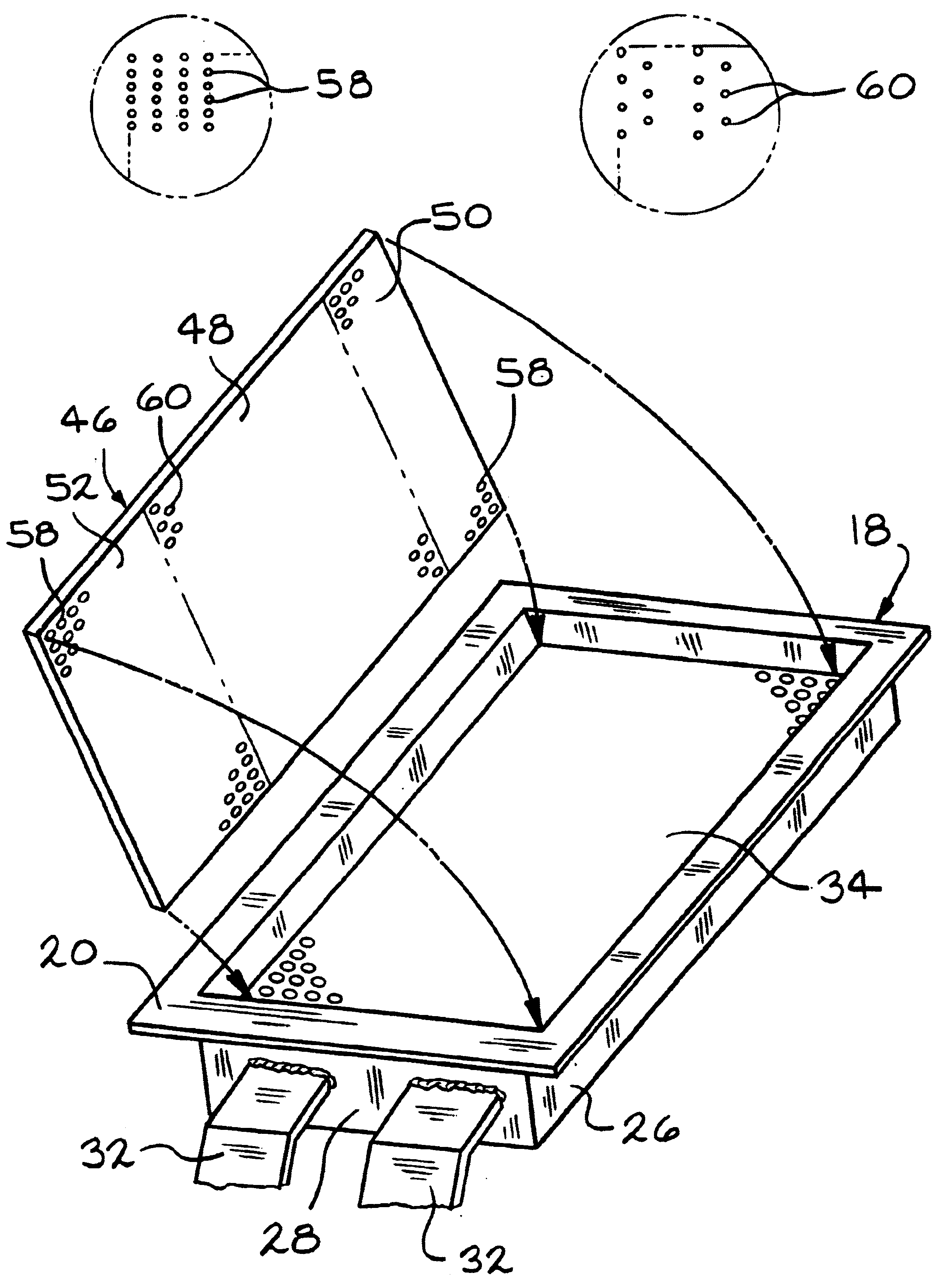
[0025]In the direct melt method for making glass fiber, a glass melting tank converts glass batch to molten glass and conditions the glass to remove most of the entrained gasses and to reduce the temperature below that used to melt the batch. Molten glass is removed from the melting tank or refining chamber through a submerged throat and into one or more channels which confines and transports the glass towards bushing legs in which a plurality of spaced apart bushings converts the molten glass into glass fiber. While almost any glass can be made into fiber, the most commonly used is well known E type glass which is a lime-alumina borosilicate. It is also known to use sodium boro-silicate glasses to make fiber. The present invention is usable with any molten material, including any organic materials and any glass compositions that can be made into a fiber using a fiberizing bushing.

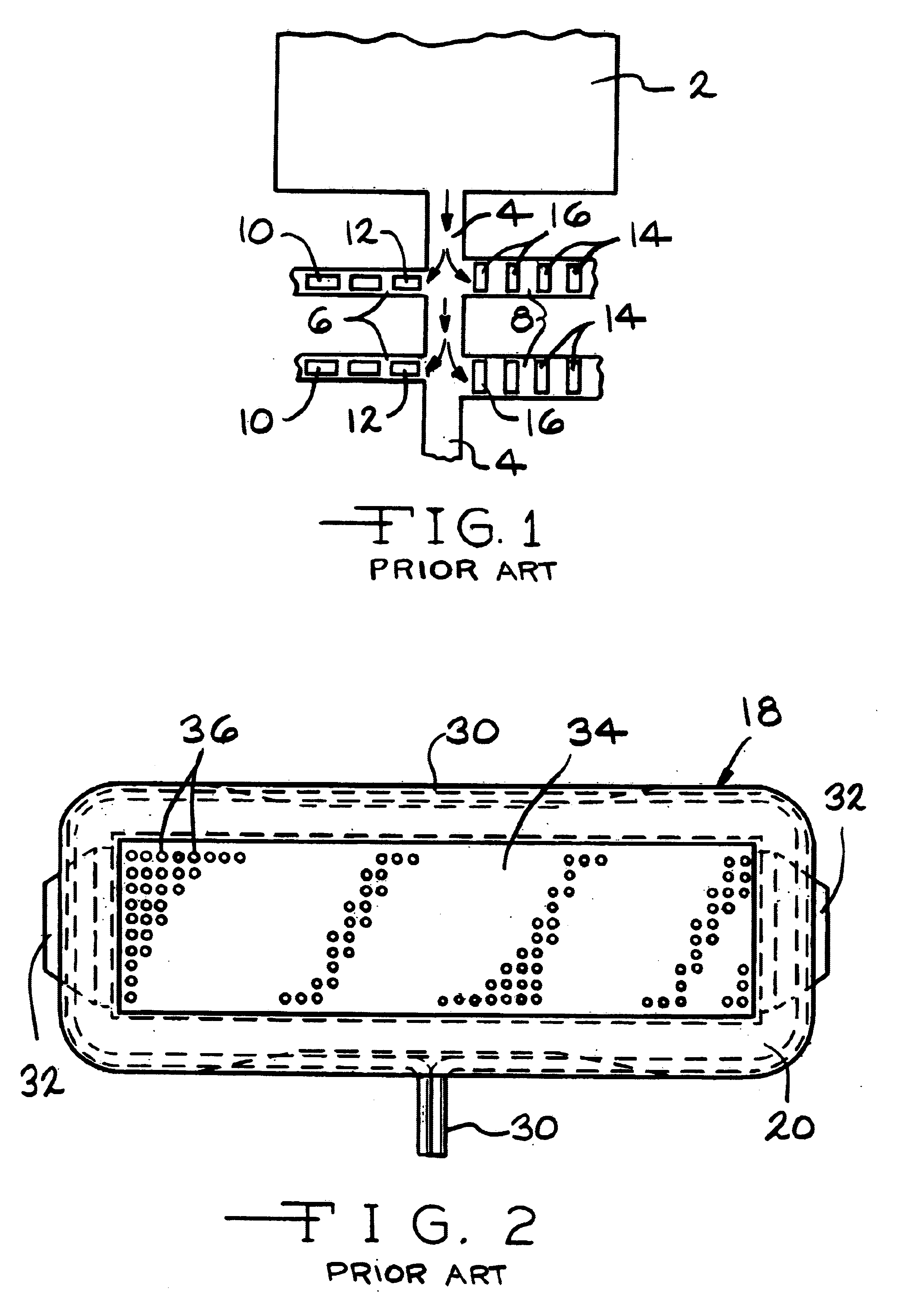
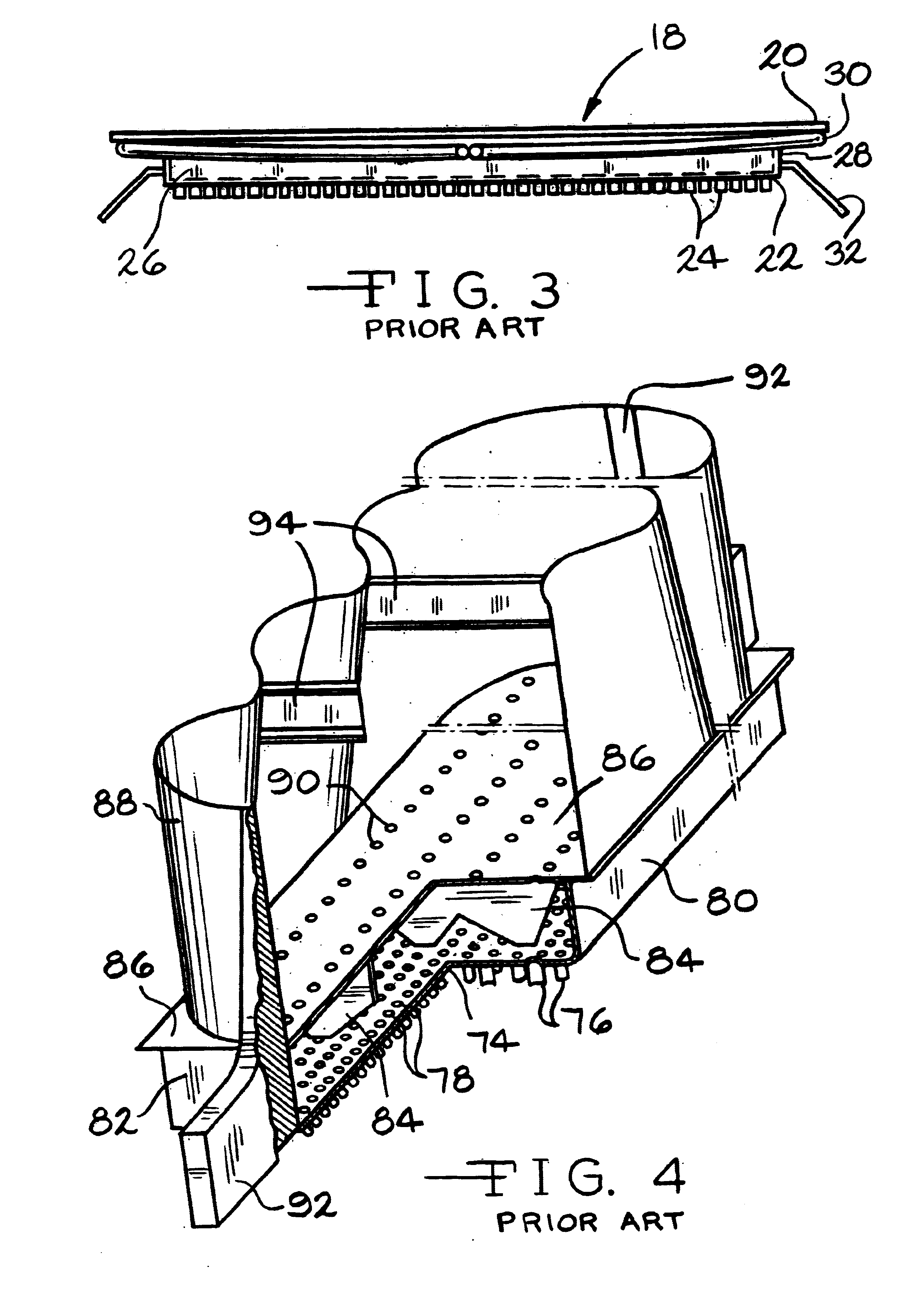
[0026]Referring to FIG. 1, which is a horizontal cross section taken below the glass line of a portion ...


PUM

PropertyMeasurementUnit
thicknessaaaaaaaaaa
thicknessaaaaaaaaaa
thicknessaaaaaaaaaa

Abstract

A bushing for fiberizing molten material, such as molten glass, having a screen mounted in the bushing spaced above the tip or orifice plate with a central portion of the screen having a significantly lower percent of hole area than the percent of hole area in end portions of the screen. This bushing improves fiberizing efficiency in channel positions of a fiberizing operation. Also, such a screen can be laid on top of a conventional screen to convert a normal bushing to a channel position bushing. Methods of using these types of bushings to improve fiberization in the channel positions and for modifying conventional bushings for other uses are also disclosed.

Description

BACKGROUND[0001]The present invention involves an improved bushing apparatus for making glass fibers and an improved method of making and using glass fiberizing bushings.[0002]In the manufacture of continuous fibers from a molten material like molten glass, the molten material is often generated by a tank furnace and distributed to a plurality of fiberizing bushings via one or more channels and one or more bushing legs connected to the channel(s). Each bushing leg comes off the channel at about 90 degrees and contains a plurality of bushings that are spaced apart. The molten material exiting the tank furnace into the channel(s) is much hotter than desired for fiberizing and the molten material entering the bushing legs is typically hotter than desired for fiberizing, particularly when the furnace is being run close to designed capacity.[0003]Precious metal bushings for making continuous glass fibers are well known, having been in use for more than 50 years. Many types of bushings ex...

Claims


Application Information

Patent Timeline
Patent Type & Authority Patents(United States)
IPC IPC(8): C03B37/022C03B37/08
CPCC03B37/08
Inventor ARTERBURN, RUSSELL DONOVAN
Owner JOHNS MANVILLE INT INC
Why Eureka
Try Eureka