In vivo joint space measurement device and method

a joint space measurement and in vivo technology, applied in the field of joint endoprosthesis systems, can solve the problems of human joints being damaged, articular cartilage covering the ends, and bearing wear problems, and achieve the effect of convenient access and accura

Active Publication Date: 2007-03-27
DEPUY PROD INC
View PDF57 Cites 232 Cited by
  • Summary
  • Abstract
  • Description
  • Claims
  • Application Information

AI Technical Summary

Problems solved by technology

Human joints can become damaged as a result of accident or illness.
Such damage can be, for example, to the articular cartilage covering the ends of the bones at the joint as well as the intra-articular cartilage between the ends of the adjacent bones of the joint.
Bearing wear is problematic in the orthopaedic field.
See, for example: U.S. Pat. No. 6,281,264, “Chemically Crosslinked Ultrahigh Molecular Weight Polyethylene for Artificial Human Joints” and U.S. Pat. No. 6,228,900 “Crosslinking of Polyethylene for Low Wear Using Radiation and Thermal Treatments.” In addition, the bearing can wear in an uneven manner if the soft tissue of the joint is or becomes unbalanced.
For example, if the soft tissue of the knee is unbalanced, the medial or lateral side of the tibial bearing could be subjected to additional stress and wear.
Both methods require use of external imaging devices, and both can be time consuming.
Both methods are prone to some measurement error due to the limited accuracy of the equipment.
Also, the accuracy of measurements of joint space taken from radiographs depends on analysis technique and bias, affecting repeatability and reproducibility.
In addition, because of the high equipment cost, it is unlikely that RSA will become a standard technique in patient monitoring.

Method used


Image

  • In vivo joint space measurement device and method
  • In vivo joint space measurement device and method
  • In vivo joint space measurement device and method

Examples


first embodiment

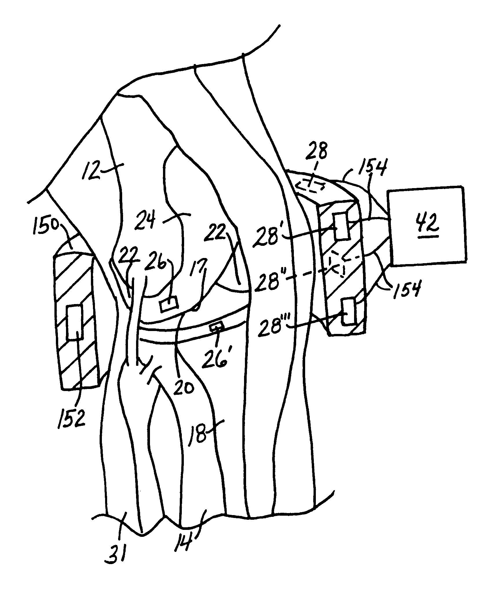
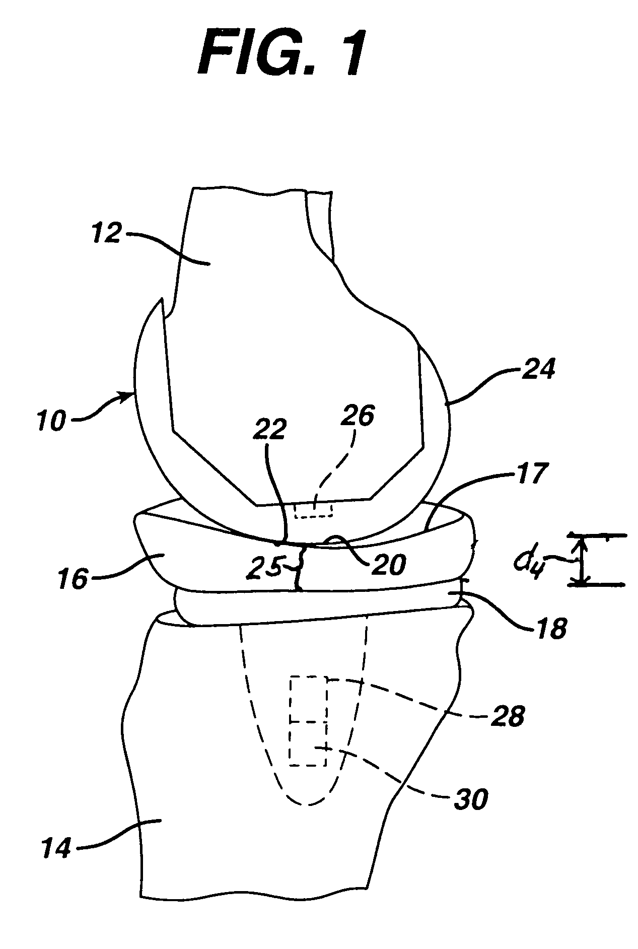
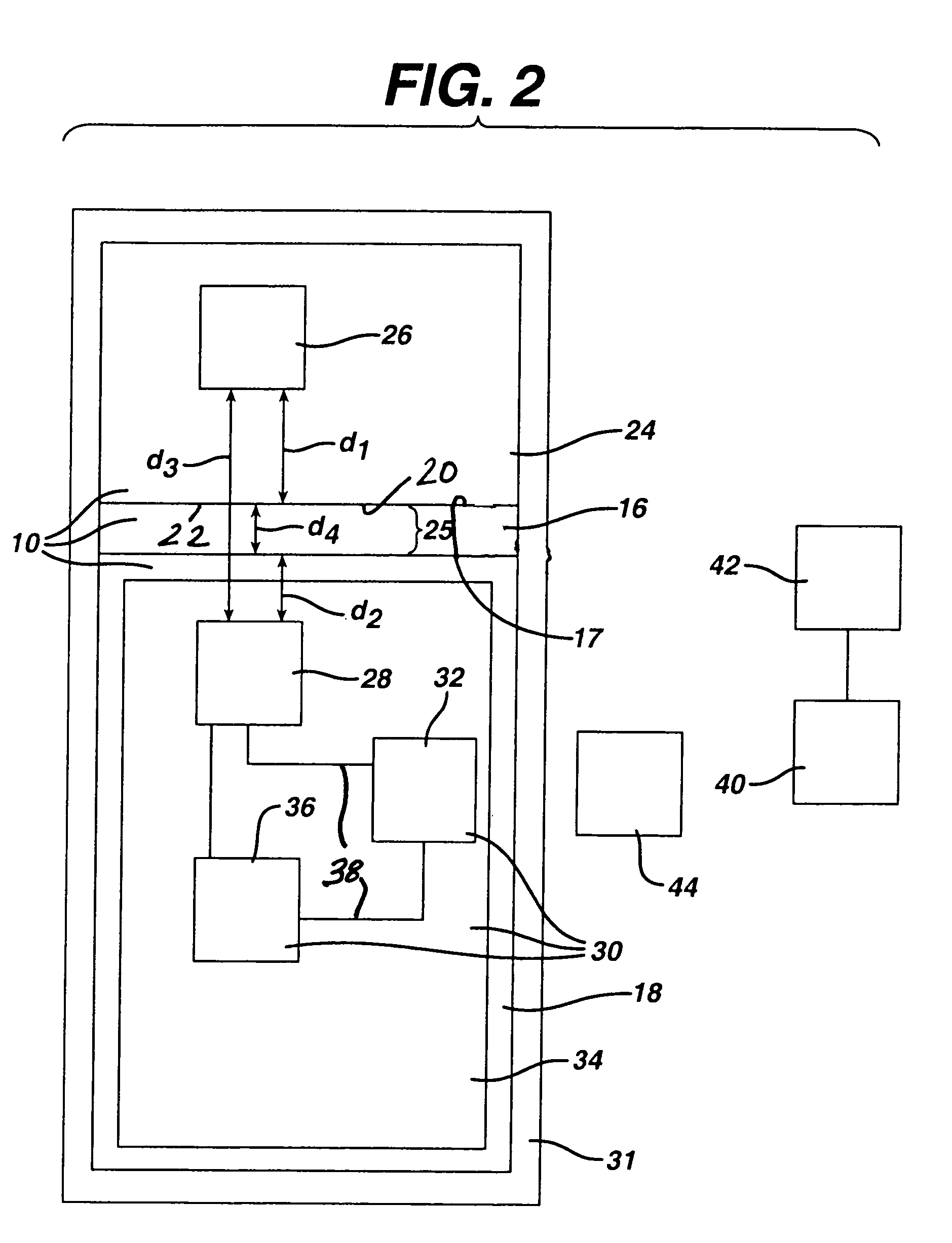
[0061]FIG. 2 illustrates the principles of the present invention schematically. As shown therein, the patient's body is represented by the large box labeled 31. The magnet that serves as the signal source 26 is illustrated as a component of the distal femoral component 24. The Hall effect transducer that serves as the sensor 28 is illustrated as a component of the proximal tibial component 18. The tibial bearing 16 is shown schematically between the femoral and tibial components 24, 18.

[0062]As shown schematically in FIG. 2, the knee endoprosthesis system 10 includes implanted electronic components 30. These electronic components 30 include a power component 32, a printed circuit board 34, a modulator / transmitter 36, wiring 38 and solder (not shown).

[0063]The power component 32 can comprise an internal power source, such as a battery, or an inductive power source such as ferrite coil. A suitable ferrite coil is a small wound coil available commercially from MicroStrain, Inc. of Will...

third embodiment

[0079]a prototype knee endoprosthesis system is illustrated in FIG. 15. As in the embodiments of FIGS. 1, 8 and 10, the prototype knee endoprosthesis system of the embodiment of FIG. 15 includes a distal femoral component 24A, proximal tibial component 18A and bearing component 16A, although in this embodiment, the proximal tibial component 18A and bearing component 16A have some different features, as described in more detail below.

[0080]As in the embodiments of FIGS. 1 and 8, in the embodiment of FIG. 15 the distance reference 28 comprises a Hall effect transducer and the signal source 26 comprises a magnet. The Hall effect transducer (distance reference 28) in the embodiment of FIGS. 15 and 16 is carried on a circuit board 34 on the proximal surface 29 of the tibial tray 18A, and fits within a recess 33 in the distal surface of the tibial bearing 16A, although it should be understood that this embodiment is a prototype and that in a final embodiment these components could be carr...


PUM


Abstract

A joint endoprosthesis system has first and second prosthetic components. The second prosthetic component has a bearing surface. The interface of the bearing surface and the first prosthetic component defines the joint articulation. A signal source and sensor are affixed on opposite sides of the joint articulation. The signal source generates a first signal that is received by the sensor. The sensor generates a second signal that has a characteristic that varies depending on the distance between the sensor and the signal source. A transmitter transmits a signal. The signal has a characteristic that varies depending on the characteristic of the second signal. This system can be used to measure a dimension of the joint space and to determine whether a dimension of the joint space has changed over time. The system may alternatively use magnets and magnetic sensors.

Description

CROSS-REFERENCE TO RELATED APPLICATIONS[0001]This application claims priority to U.S. Provisional Application Ser. No. 60 / 486,615 filed on Jul. 11, 2003 by Mark R. DiSilvestro, entitled “In Vivo Joint Space Measurement Device and Method,” which is incorporated by reference herein in its entirety.FIELD OF THE INVENTION[0002]The present invention relates to joint endoprostheses systems.BACKGROUND OF THE INVENTION[0003]Human joints can become damaged as a result of accident or illness. Such damage can be, for example, to the articular cartilage covering the ends of the bones at the joint as well as the intra-articular cartilage between the ends of the adjacent bones of the joint. When the damage to the joint is severe, a joint endoprosthesis can be implanted to improve the comfort and mobility of the patient.[0004]Joint endoprostheses have been developed to replace native tissue of several human joints. There are a variety of knee prostheses, hip prostheses, shoulder prostheses, ankle ...

Claims


Application Information

Patent Timeline
Patent Type & Authority Patents(United States)
IPC IPC(8): A61F2/30A61B5/103A61B5/07A61B5/107A61B19/00A61FA61F2/00A61F2/02A61F2/32A61F2/34A61F2/36A61F2/38A61F2/40A61F2/46
CPCA61B5/076A61B5/4528A61B19/46A61F2/32A61F2/38A61F2/40A61F2/4657A61B5/1076A61F2250/0037A61B2019/461A61F2/34A61F2/36A61F2/367A61F2/3859A61F2/389A61F2/4081A61F2002/30079A61F2002/30133A61F2002/30326A61F2002/30589A61F2002/30668A61F2002/3067A61F2002/30795A61F2002/30807A61F2002/30878A61F2002/30884A61F2002/30892A61F2002/3611A61F2002/4018A61F2002/4062A61F2002/4661A61F2002/4698A61F2002/488A61F2210/009A61F2230/0015A61F2250/0001A61F2250/0002A61B90/06A61B2090/061A61F2/488
Inventor DISILVESTRO, MARK R.SHERMAN, JASON T.DIETZ, TERRY L.
Owner DEPUY PROD INC
Why Eureka
Try Eureka