Battery charge/discharge monitoring circuit and method

a battery and monitoring circuit technology, applied in the field can solve the problems of inability to precisely determine the battery capacity, inability to detect an extremely large error, etc., to reduce the dead time in capacitor discharge, improve the accuracy of battery capacity or residual capacity measurement, and reduce the effect of battery charge/discharge monitoring circuit siz

Active Publication Date: 2007-03-27
SEMICON COMPONENTS IND LLC
View PDF13 Cites 14 Cited by
  • Summary
  • Abstract
  • Description
  • Claims
  • Application Information

AI Technical Summary

Benefits of technology

[0013]According to this battery charge / discharge monitoring circuit, the numbers of times the outputs of the at least one comparator for the first and second terminal capacitors change are counted, and the difference between the numbers of times change takes place is output for the first and second terminals. Therefore, it is possible to eliminate error signal component such as ground level variation and common noise in the battery charge / discharge monitoring circuit by taking the difference in number of times the outputs of the at least one comparator change between the two terminals.
[0032]Discharge and charge monitoring can be implemented with a single circuit system. Even in the case of an extremely small potential change detected from individual terminals of the current detection resistor—the resistor provided for detecting battery charge or discharge current, it is possible to precisely monitor the amount of charge or discharge current, thus allowing for accurate measurement of the battery capacity or residual capacity.

Problems solved by technology

This difference in ground level leads to an innegligible error in detecting an extremely small voltage change for precise judgment of the battery capacity when charge monitoring and discharge monitoring are conducted alternately.
Besides, if error signal component such as common noise accumulates in both circuit systems, it becomes impossible to precisely determine the battery capacity.

Method used


Image

  • Battery charge/discharge monitoring circuit and method
  • Battery charge/discharge monitoring circuit and method
  • Battery charge/discharge monitoring circuit and method

Examples


first embodiment

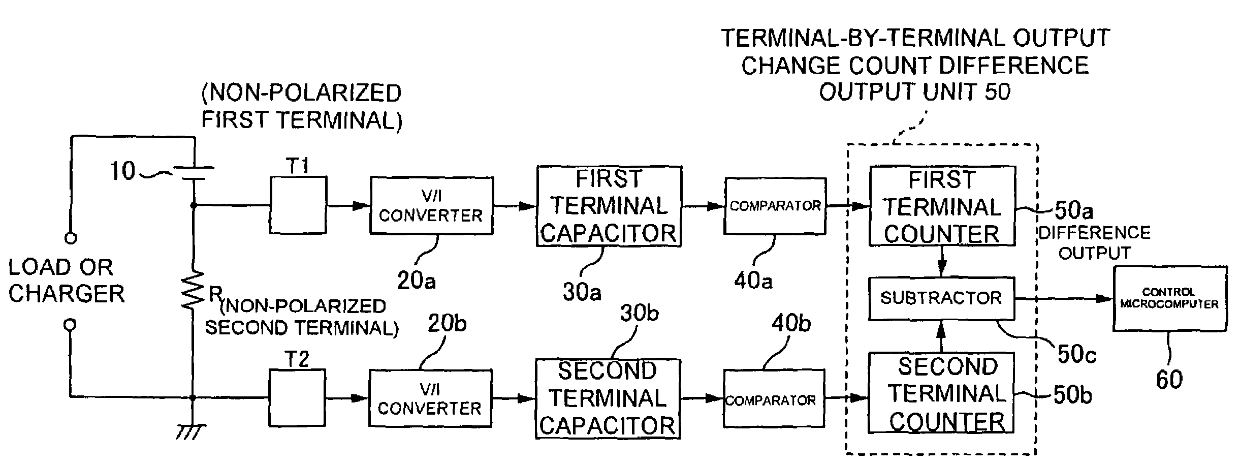
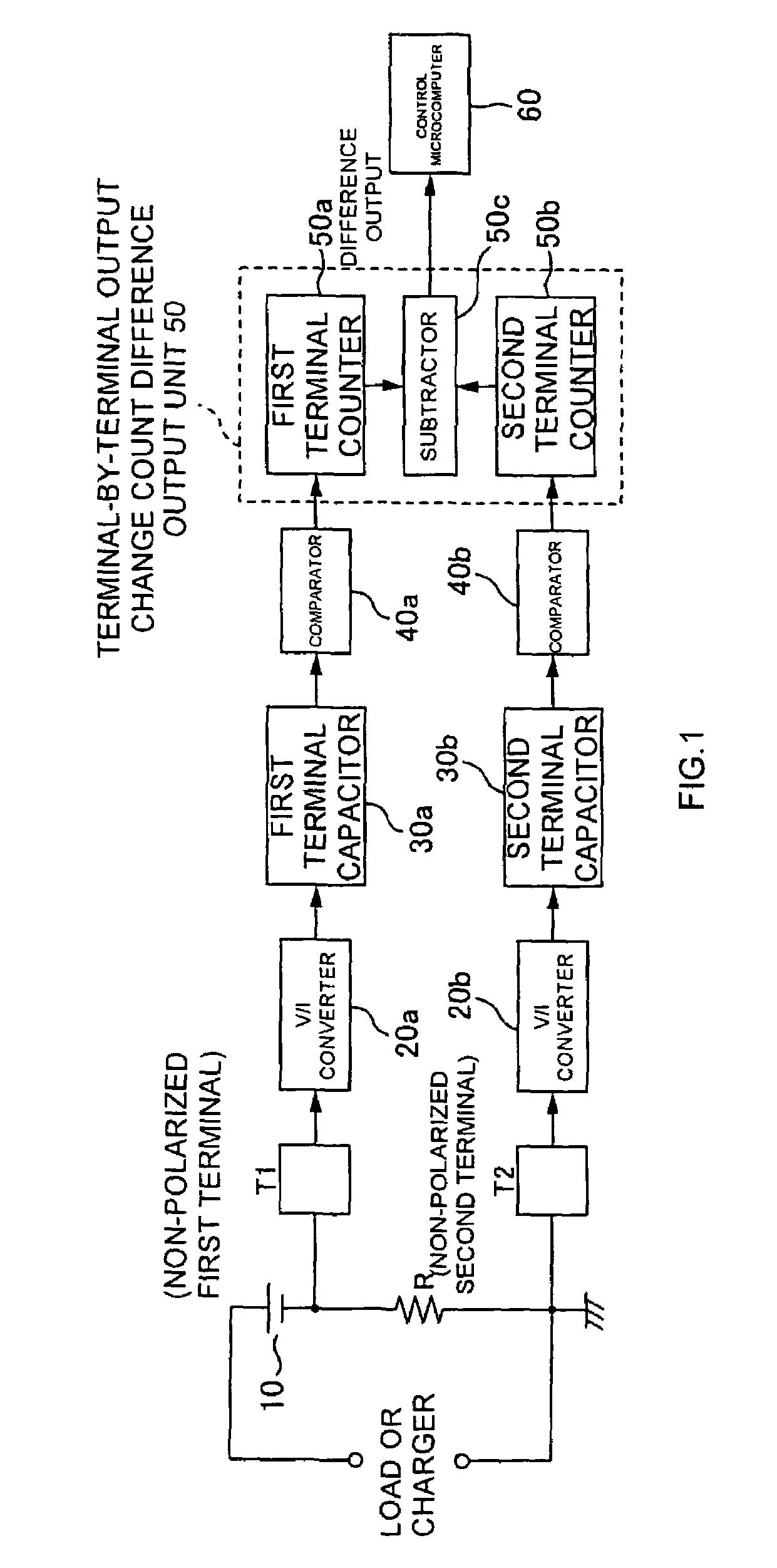
[0039]As an example, a current detection resistor R for detecting the charge or discharge current of a battery 10 is connected in series with the battery 10 as shown in FIG. 1. A load supplied with power by the battery 10 or a charger for charging the battery 10 is connected to the series circuit including the battery 10 and the current detection resistor R. A first terminal T1 is connected to one of the terminals (first terminal) of the current detection resistor R, whereas a second terminal T2 is connected to the other terminal (second terminal). The first and second terminals T1 and T2 are non-polarized, which means they are battery polarity insensitive. Also, either of the terminals (e.g., the second terminal T2) is grounded. Potential detection systems for the first and second terminals T1 and T2, namely, the terminals of the current detection resistor R, are separate from each other.

[0040]That is, there are provided terminal-specific charge / discharge monitoring systems equippe...

second embodiment

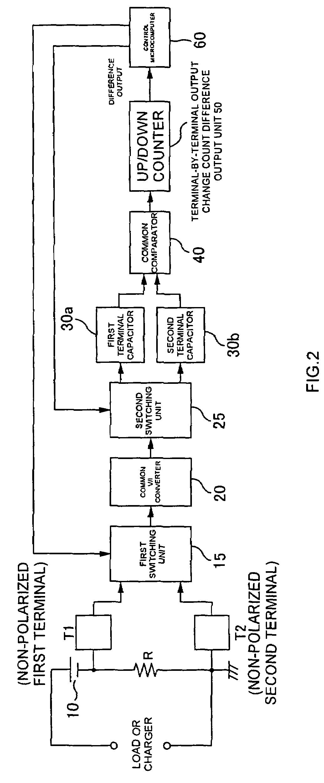
[0050]In contrast to the first embodiment comprising charge / discharge monitoring systems, one for the first terminal and the other for the second terminal, the present embodiment combines the charge / discharge monitoring systems into a single system except for the first and second terminal capacitors 30a and 30b. This makes it possible to resolve the impact of variations in circuit elements between a plurality of terminal-specific charge / discharge monitoring systems as compared with the first embodiment having the first and second terminal-specific charge / discharge monitoring systems. Therefore, it is possible to provide improved accuracy in the output of the terminal-by-terminal output change count difference output unit 50. This also allows for component count reduction, thus downsizing the circuit scale, which in turn ensures noise reduction, power and space savings and cost reduction.

[0051]In detail, the current detection resistor R for detecting the battery 10's charge or discha...

first example

Circuit Configuration

[0062]A specific circuit configuration example of the first embodiment shown in FIG. 1 is illustrated in FIG. 3. Since the matters discussed with reference to FIG. 1 are common, the description will focus on specific circuit configurations of the individual units.

[0063]First of all, a specific configuration example of the voltage / current converters 20a and 20b will be described. Since the voltage / current converters 20a and 20b are identical in configuration, a description will be made together as appropriate.

[0064]As shown in FIG. 3, gates of transistors (p-type channel MOSFETs) Tr20ai and Tr20bi are connected to the first and second terminals T1 and T2 to detect an extremely small potential change. The drains of the transistors Tr20ai and Tr20bi are grounded, whereas their sources are connected to the inverted input terminals of op-amps Amp20a and Amp20b via resistors R20ai and R20bi.

[0065]A series circuit including a resistor R20aii and a transistor (p-type c...


PUM

PropertyMeasurementUnit
charge currentaaaaaaaaaa
discharge currentaaaaaaaaaa
integrated voltageaaaaaaaaaa

Abstract

A circuit for monitoring charge / discharge of a battery is disclosed. The circuit may comprise first and second terminal capacitors disposed for first and second terminals of a current detection resistor connected to a battery. The first and second terminal capacitors may develop an integrated voltage responsive to the charge / discharge current obtained from the individual terminals. The circuit may also include at least one comparator for comparing the individual integrated voltages developed by the first and second terminal capacitors with a reference voltage, the comparator having respective outputs which change when the individual integrated voltages reach the reference voltage. A terminal-by-terminal output change count difference output unit may count the number of times the output of the comparator changes and may output the difference between the number of times of change corresponding to the first terminal and the number of times of change corresponding to the second terminal.

Description

NOTICE OF COPYRIGHTS AND TRADE DRESS[0001]A portion of the disclosure of this patent document contains material which is subject to copyright protection. This patent document may show and / or describe matter which is or may become trade dress of the owner. The copyright and trade dress owner has no objection to the facsimile reproduction by any one of the patent disclosure as it appears in the Patent and Trademark Office patent files or records, but otherwise reserves all copyright and trade dress rights whatsoever.RELATED APPLICATION INFORMATION[0002]This application claims the benefit of priority to Japanese Patent Application Nos. 2003-121754 filed on Apr. 25, 2003 and 2003-338864 filed on Sep. 29, 2003, of which contents are incorporated herein by reference.BACKGROUND OF THE INVENTION[0003]1. Field of the Invention[0004]The present invention relates to a circuit for and a method of monitoring charge / discharge of a battery.[0005]2. Description of the Related Art[0006]In the batter...

Claims


Application Information

Patent Timeline
Patent Type & Authority Patents(United States)
IPC IPC(8): G01N27/416G01R31/36H02J7/04H02J7/00
CPCG01R31/3613G01R31/3832H05B3/44H05B3/56
Inventor YAMADA, SUSUMU
Owner SEMICON COMPONENTS IND LLC
Why Eureka
Try Eureka