Electrostatic device

Inactive Publication Date: 2007-03-27
DABBAJ RAD H
View PDF16 Cites 35 Cited by
  • Summary
  • Abstract
  • Description
  • Claims
  • Application Information

AI Technical Summary

Benefits of technology

[0023]It is possible with the present invention to provide new types of actuators and sensors which can be operated at lower voltages making them more compatible with integrated circuits. The actuators can have improved deflection versus voltage characteristics and improved trade-off betw

Problems solved by technology

This suffers from the inextricable link between the gap length and useful deflection, with the latter usually much less than but not exceeding the gap itself.
Larger deflections require larger gaps and consequential large voltages that are very often incompatible with standard IC drive electronics.
Comb-drive actuators suffer from several problems including: relatively large support/springs passive area, limited out-of-plane movement, difficulty in

Method used


Image

  • Electrostatic device
  • Electrostatic device
  • Electrostatic device

Examples


Embodiment Construction

[0039]It will be apparent to the skilled person that the actuators described herein could also be used as sensors and therefore the term “device” is intended to encompass both actuators and sensors. Furthermore, on the whole the description focuses on actuators for simplicity only and it is intended that equivalent sensors are also encompassed.

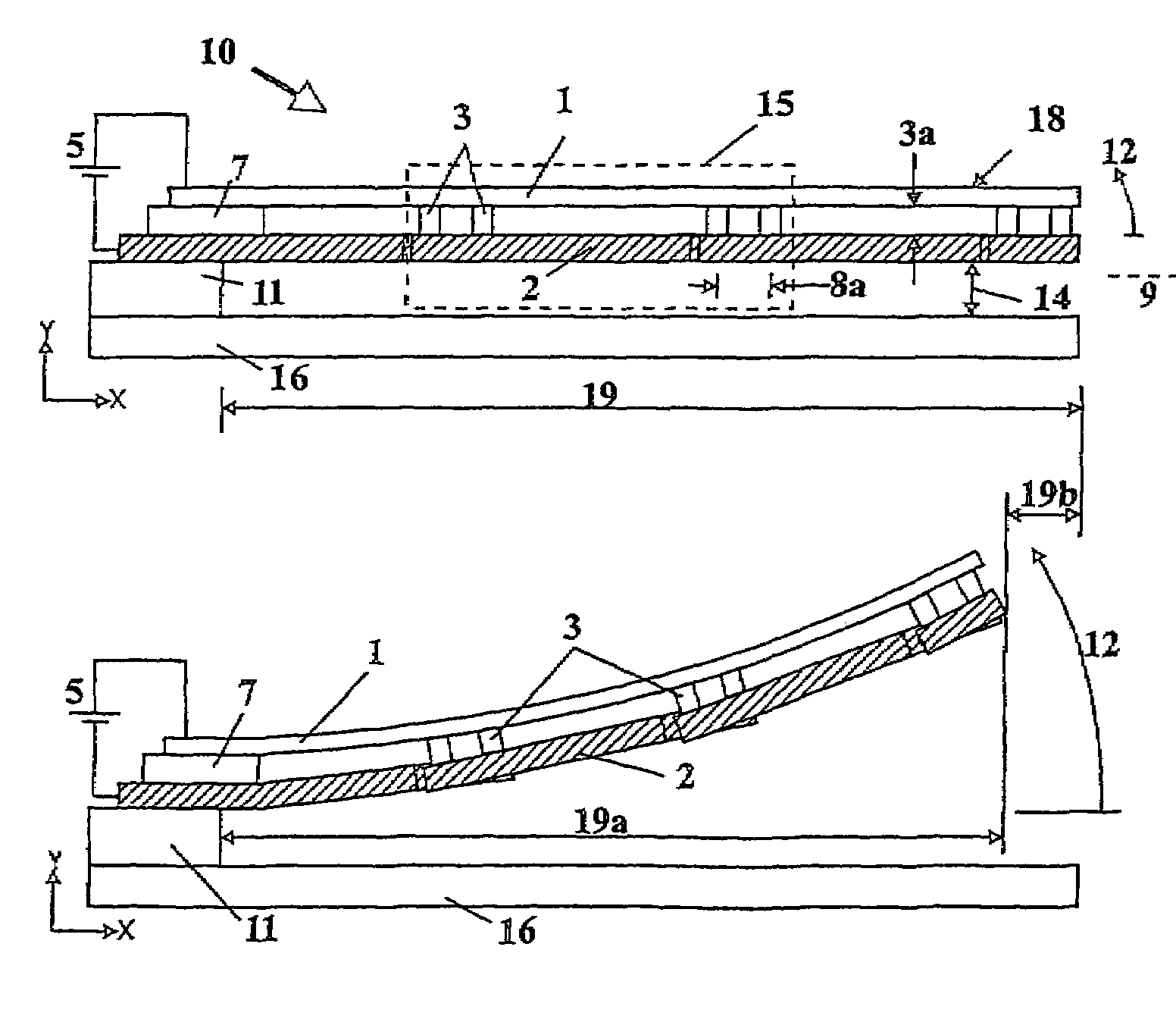
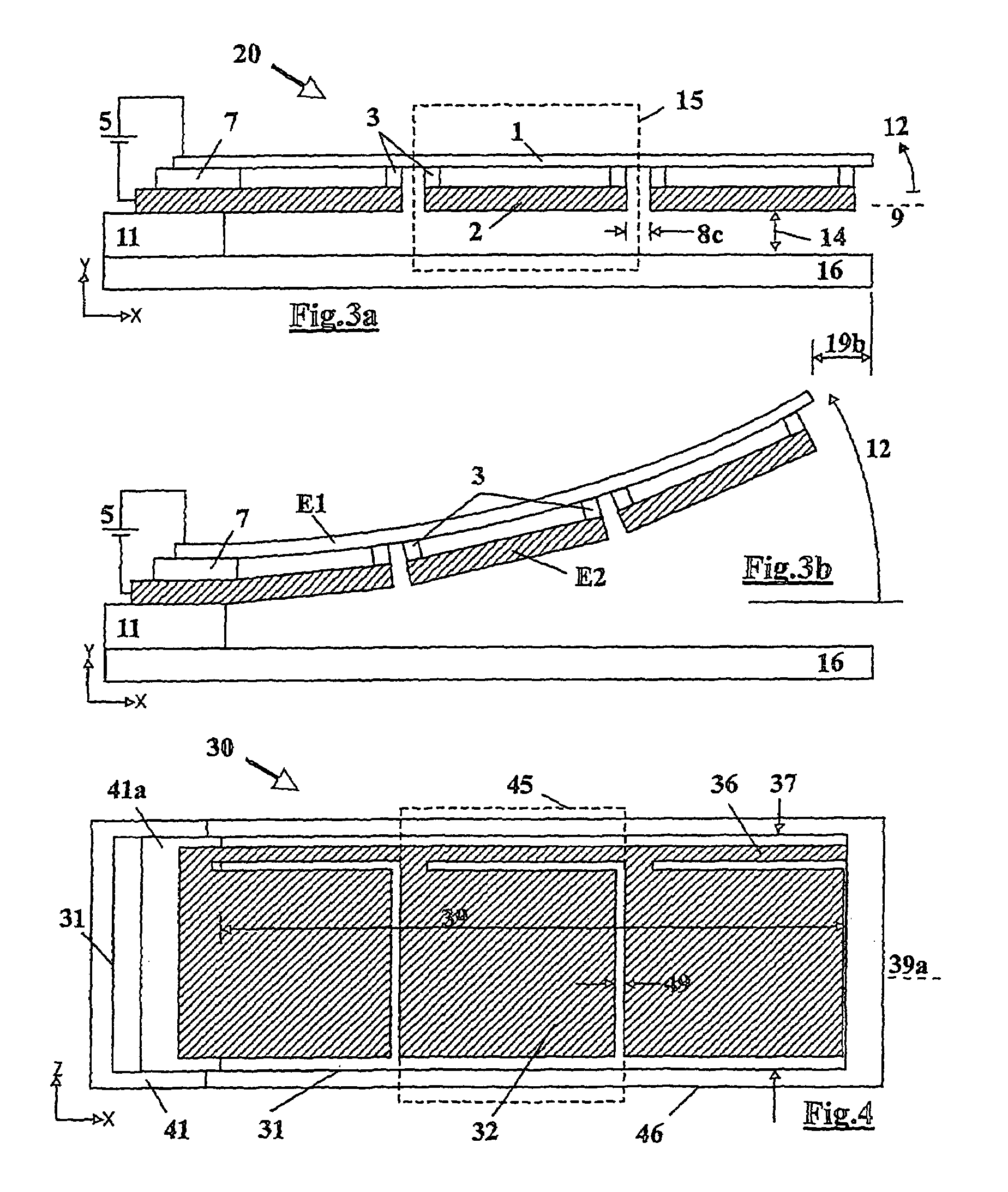
[0040]In this specification, electrode E1 refers to members 1, 31, 91 and 101 described below, and electrode E2 refers to members 2, 32, 92 and 102 described below. Devices able to deflect or bend about one or more axes may be referred to herein as single axis devices, double axis devices and so on.

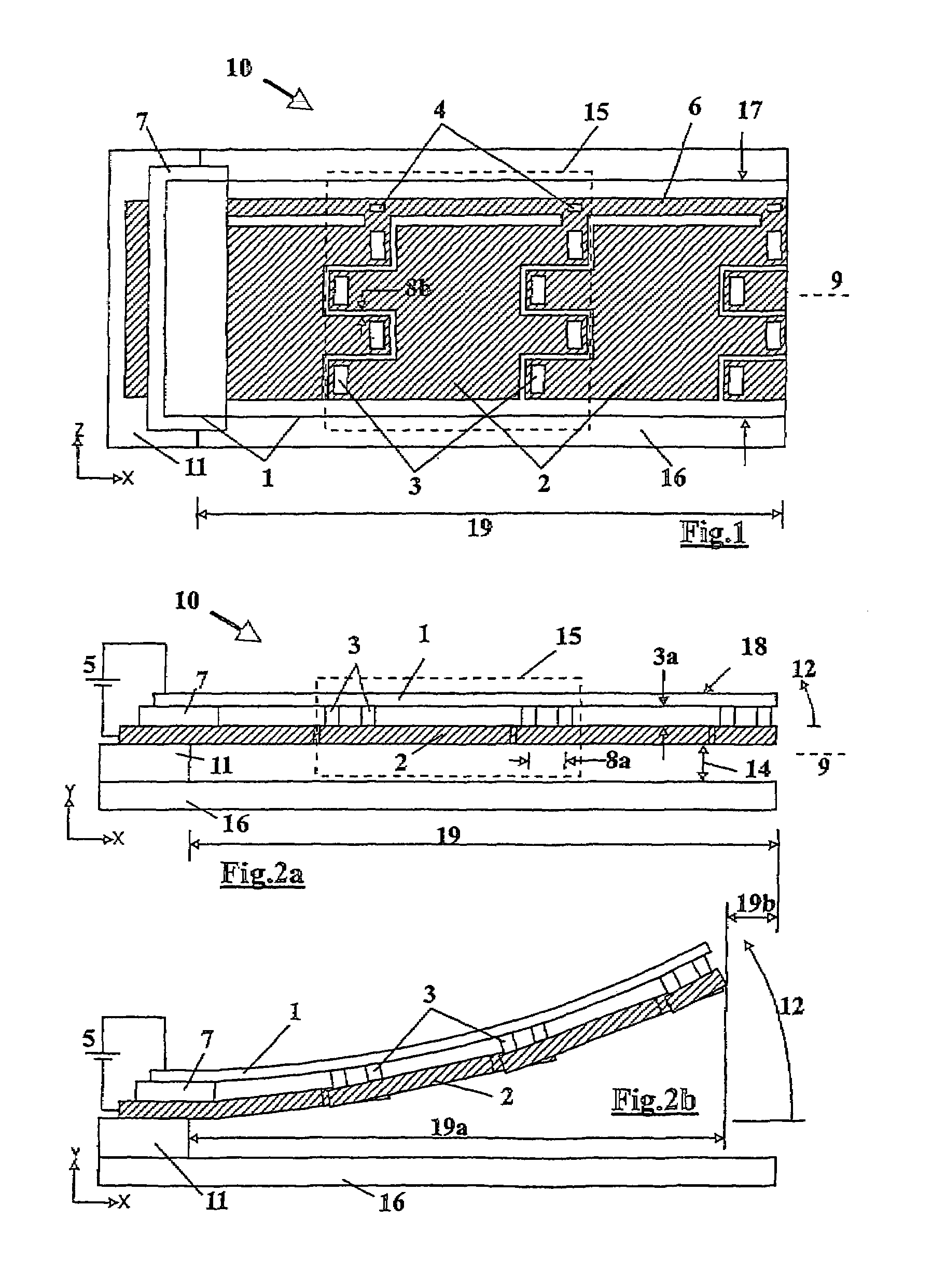
[0041]Referring to FIGS. 1, 2a and 2b the embodiment of device shown can deflect about one axis (in this example about the Z-axis). FIG. 1 shows the device in plan view, while FIG. 2a shows a side elevational view of the device. For ease of understanding, FIG. 1 shows the first layer in outline only, but is shown in solid form in FIGS. 2a and 2b.

[0...


PUM


Abstract

An electrostatic device (10) includes a first flexible electrode (1) on which a plurality of second electrodes (2) are mounted so as to move with the first electrode (1). Upon the application of an electrical charge, the or each second electrode (2) causes deflection of the first electrode (1) which deflection is enhanced by the movement of the second electrode therewith. A variety of different designs of the device are possible to provide movement of the first electrode in a plurality of directions and also different types of in and out of plane movement, including rotation and twisting. The structure enables the device to operate at voltage levels compatible with integrated circuits and for the device to be manufactured using integrated circuit manufacturing techniques.

Description

FIELD OF THE INVENTION[0001]The present invention relates to electrostatic devices, in particular actuators and sensors of the type commonly referred to as Micro-Electro-Mechanical Systems (MEMS) or micromachined devices.BACKGROUND OF THE INVENTION[0002]Generally, prior art electrostatic transducer devices, whether actuators or sensors, comprise first and second members connected to a drive voltage-source. The resulting attractive electrostatic forces cause at least one of the members to move towards the other. For this purpose, the members are normally made of conductive material, such as metals and doped-polysilicon to facilitate charging and discharging and ensure proper operation.[0003]Prior art devices are disclosed, for example, in the “Micromachined Transducers Sourcebook” by G. T. A. Kovacs, WCB / McGraw-Hill, 1998, at pages 278 to 281, such as the classic cantilever actuator having a movable electrode suspended above a stationary counter-electrode by a gap. This suffers from ...

Claims


Application Information

Patent Timeline
IPC IPC(8): H01H51/22B81B3/00H02N1/00
CPCH01G5/18H02N1/006
Inventor DABBAJ, RAD H.
Owner DABBAJ RAD H
Why Eureka
Try Eureka