
Efficient use of detectors for random number generation

a technology of random number generation and detectors, applied in the field of random number generators, to achieve the effect of maximizing efficient detector usage and reducing dark count rates

Active Publication Date: 2007-03-27
MAGIQ TECH INC
View PDF5 Cites 18 Cited by
  • Summary
  • Abstract
  • Description
  • Claims
  • Application Information

AI Technical Summary

Benefits of technology

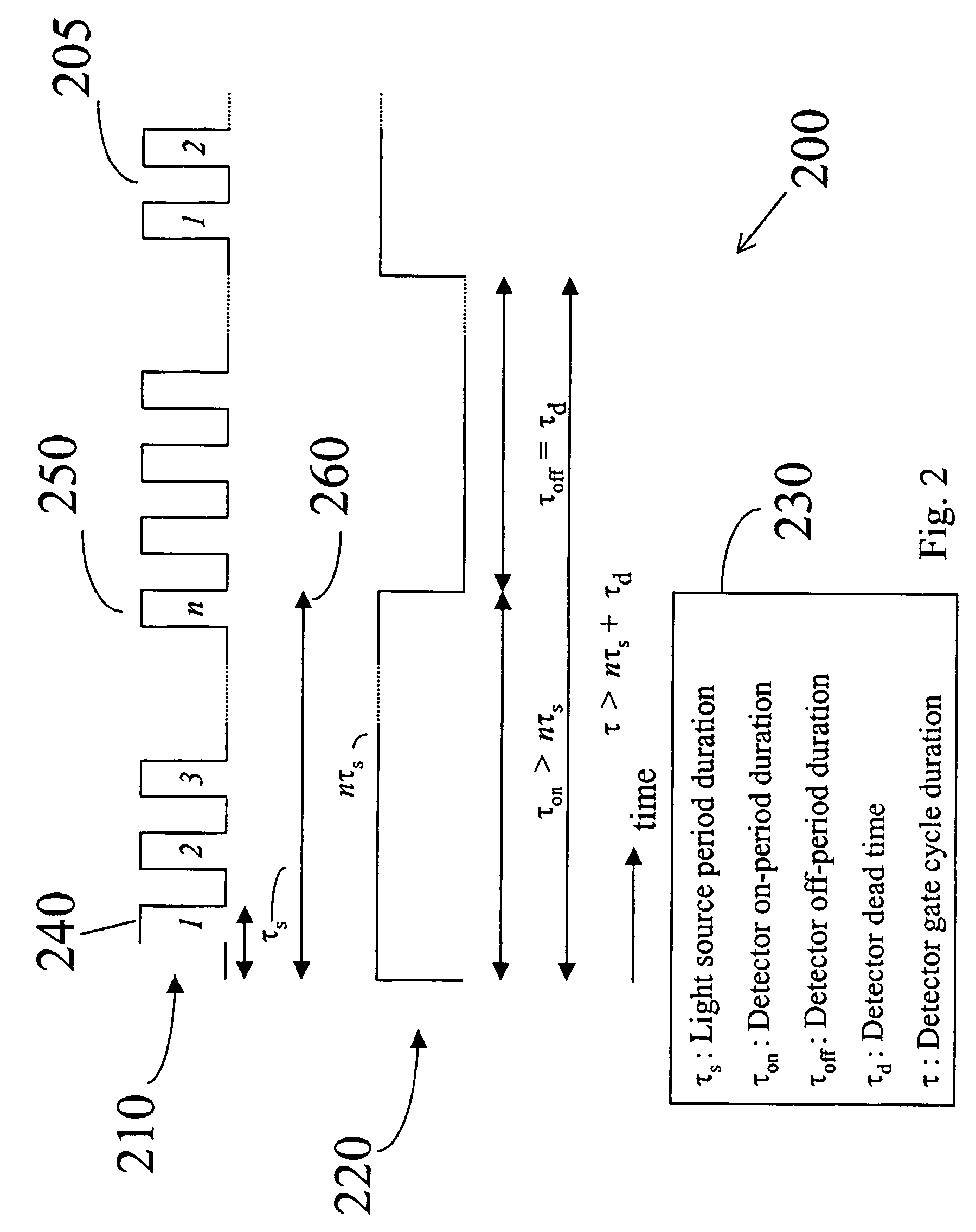
[0030]The cycle repeats to create the next random integer from the new sequence of n pulses. The microprocessor / memory device collects the random integers, which may be statistically correlated and biased, and converts a string of random integers into a string of statistically independent random bits using computational operations. If the random integers created by successful detections are statistically independent already, each integer represents log2n random bits. As a result, for short on-periods compared to the off-periods, this method can provide a random digital number generation rate that approaches R=log2n / τd. This rate can be substantially larger than 1 / τd. Moreover, the gating technique, which turns off the detector during the off-period, reduces the dark count rates relative to a detector that remains biased continuously.
[0031]A second method that uses a preferred embodiment of the apparatus is an adaptation of the first method. The controller in the second method breaks the on-period into n on- and off-sub-periods electronically. During the on-sub-period the controller triggers the gating electronics to turn on the detector only during the time windows that correspond to the expected arrival times of the n pulses. The off-sub-periods are the time windows between pulses, during which the gating electronics turn off the detector. Otherwise, this method operates like the first. This second method lowers the dark count rate further since the light pulse durations and therefore the on-sub-periods may be much shorter than the time between light pulses, given by the inverse of the source repetition rate. For short on-periods compared to off-periods, this method can provide a random bit generation rate that approaches R=log2n / τd.
[0032]A third method of using the apparatus can work as an adaptation of either of the first two methods. In the first two methods the time window encompassing the fixed number of n pulses defines each detection on-period. By relaxing the constraint of a fixed on-period duration, the dark count rate can be reduced and the speed of those methods can be increased. In this third method the off-period begins immediately after a successful detection event. The detector electronics sends a feedback electronic signal to the controller at the time of a successful detection event. Immediately after receiving that signal, the controller sends a signal to the gating electronics to lower the detector voltage below breakdown and initiate the off-period. This action is a departure from the first two methods, where the controller waits until the end of the nth pulse to initiate the off-period. The system now waits an off-period equal to the dead time before the cycle begins again with a source pulse. The average on-period now has a duration that is shorter than the previous two methods, which reduces the dark count probability. In addition, by initiating the off-period after a successful detection, this method prevents dark counts from after-pulsing. These may occur in the first two methods since the gating electronics maintain or raise the bias voltage above breakdown before the detection avalanche has quenched fully. For short on-periods compared to off-periods, this method can provide a random bit generation rate that approaches R=log2n / τd.
[0034]Generally, the invention's use of random events from successive sequences of n discrete possibilities provides a novel way to produce random numbers. Simultaneously, the invention provides a method to reduce dark count rates and to maximize efficient detector usage when implemented with a preferred embodiment of an apparatus that uses dim light pulses.

Problems solved by technology

Thermal noise in electronics and radioactive decay are believed to provide truly random events.

Method used


Image

  • Efficient use of detectors for random number generation
  • Efficient use of detectors for random number generation
  • Efficient use of detectors for random number generation

Examples


Embodiment Construction

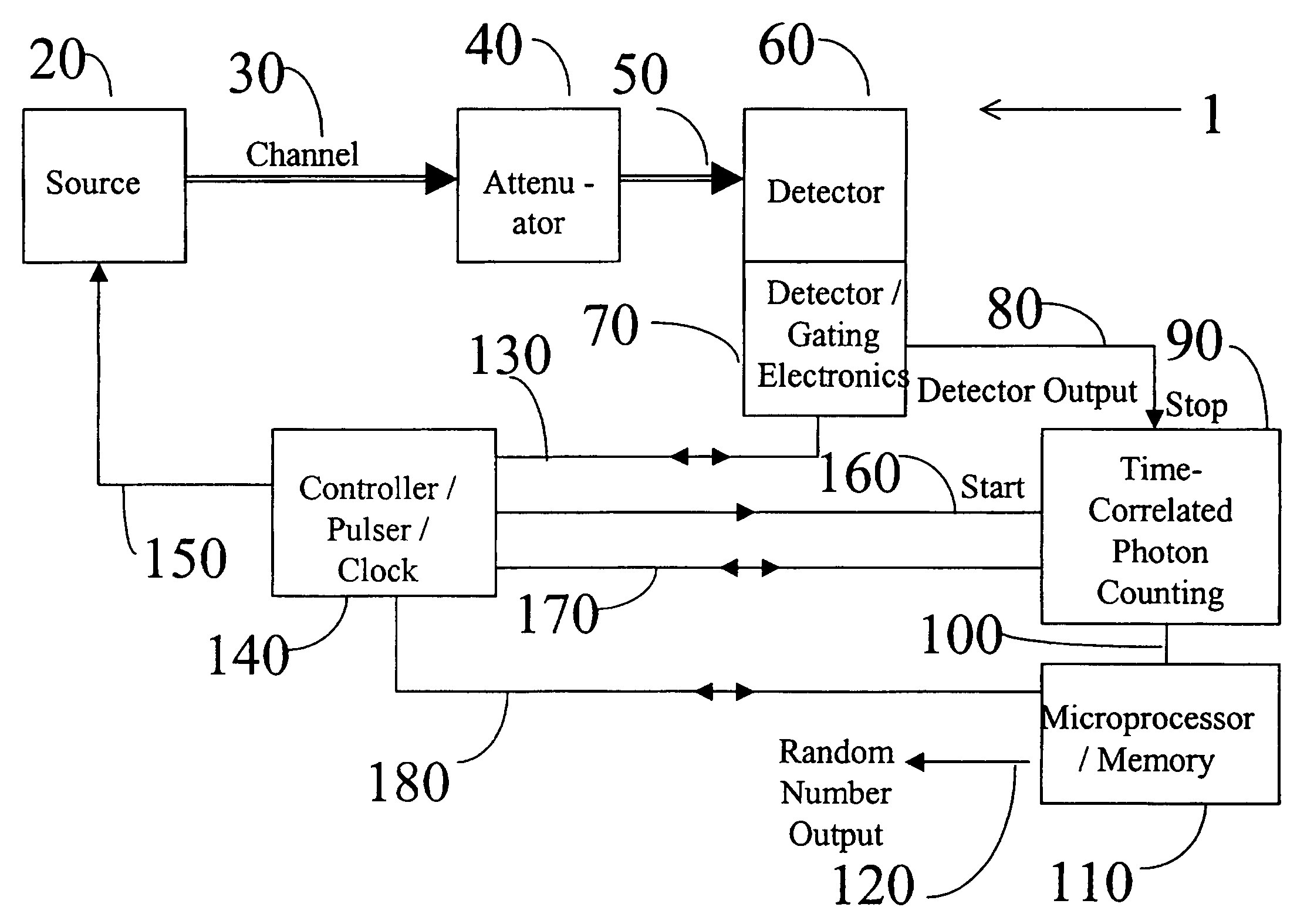
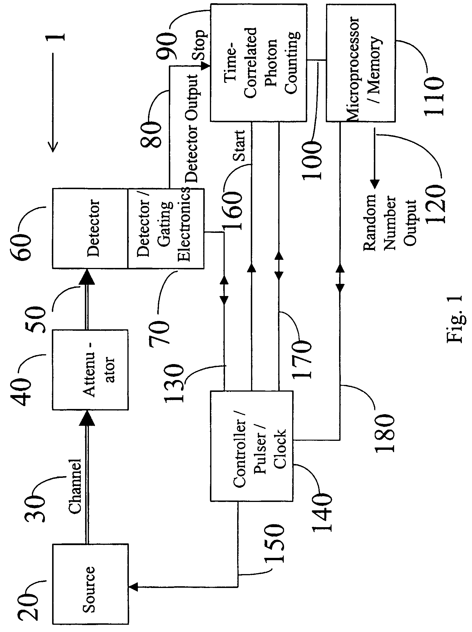
[0040]FIG. 1 shows a system 1. System 1 includes photon or optical pulse source 20, light conducting channel 30, attenuator 40, light conducting channel 50, detector 60, detector gating electronics 70, detector output 80, time correlated photon counting 90, data line 100, microprocessor / memory 110, random number output 120, control / data line 130, controller / pulser / clock 140, control line 150, control line 160, control / data line 170, and control / data line 180.

[0041]Source 20 produces a plurality of sequences of n pulses, which are plotted as source power versus time in FIGS. 2, 3, and 4 for different methods of using the preferred embodiment. Source 20 may consist of a coherent light source or an incoherent light source. Source 20 emits pulses directly or emits continuous light from which a pulser or amplitude modulator slices pulses. Channel 30 conveys photons from source 20 to attenuator 40. If source 20 provides sufficiently low enough intensity pulses, attenuator 40 is not necess...


PUM


Abstract

Apparatus for and methods of random number generation are disclosed, wherein a detector receives a group of n light pulses having single-photon intensity levels. Each of the n light pulses has a probability of less than one to produce a successful detection event at its time of arrival at the detector, and the detector is adapted to detect only one of the n pulses in the group. This single detection per group is thus a discrete random event that occurs only during one of n fixed time slots. The random event occurring during one of n timeslots is converted into a corresponding random integer from 1 to n. A series of such random numbers is generated by using a plurality of groups of n light pulses.

Description

CROSS-REFERENCE TO RELATED APPLICATIONS[0001]This application claims priority under 35 USC 119(e) and the Paris Convention to U.S. provisional application Ser. No. 60 / 289,591, filed May 9, 2001. The entire contents of that application are hereby incorporated by reference.BACKGROUND OF THE INVENTION[0002]1. Field of the Invention[0003]The invention relates to random number generators.[0004]2. Description of the Background[0005]A Random Number Generator (RNG) is a variable X whose value takes on a sequence of numbers in which the probability of any particular sequence is equally likely. The idea of random number generation refers to the probability of generation of any sequence being equal.[0006]Random numbers mean sets or sequences of numbers generated by a RNG.[0007]Pseudo-random numbers mean any distribution or sequence of numbers produced by a deterministic algorithm. Conventional software-based random number generators (RNGs) produce pseudo-random numbers.[0008]True-random number...

Claims


Application Information

Patent Timeline
Patent Type & Authority Patents(United States)
IPC IPC(8): G06F7/58G06F1/02
CPCH04L9/0852G06F7/588
Inventor LUTKENHAUS, NORBERTCOHEN, JAYSON L.LO, HOI-KWONG
Owner MAGIQ TECH INC
Learn More