Double-clutch transmission architecture for a motor vehicle

a transmission architecture and motor vehicle technology, applied in mechanical equipment, transportation and packaging, gearing, etc., can solve problems such as inability to permit, and achieve the effects of reducing manufacturing costs, reducing space occupation, and simplifying structur

Active Publication Date: 2007-04-03
CENT RICERCHE FIAT SCPA
View PDF13 Cites 19 Cited by
  • Summary
  • Abstract
  • Description
  • Claims
  • Application Information

AI Technical Summary

Benefits of technology

[0009]It is an object of the present invention to provide a double-clutch transmission architecture for a motor vehicle, with six or more gear ratios, which has a simpler structure, takes up less space and has a lower manufacturing cost than the prior art discussed above.
[0011]Thanks to the configuration defined in claim 1, one slidable sleeve and its associated actuator are eliminated, and therefore the complexity, the dimensions and the manufacturing cost of the transmission are reduced. In addition, this configuration can easily be obtained from an ordinary single-clutch transmission, whether manual or robotised.

Problems solved by technology

Such a configuration obviously does not permit to shift from the penultimate gear ratio to the last gear ratio, and vice-versa, in so-called power-shift mode, that is without interruption in the transmission of torque.

Method used


Image

  • Double-clutch transmission architecture for a motor vehicle
  • Double-clutch transmission architecture for a motor vehicle
  • Double-clutch transmission architecture for a motor vehicle

Examples


first embodiment

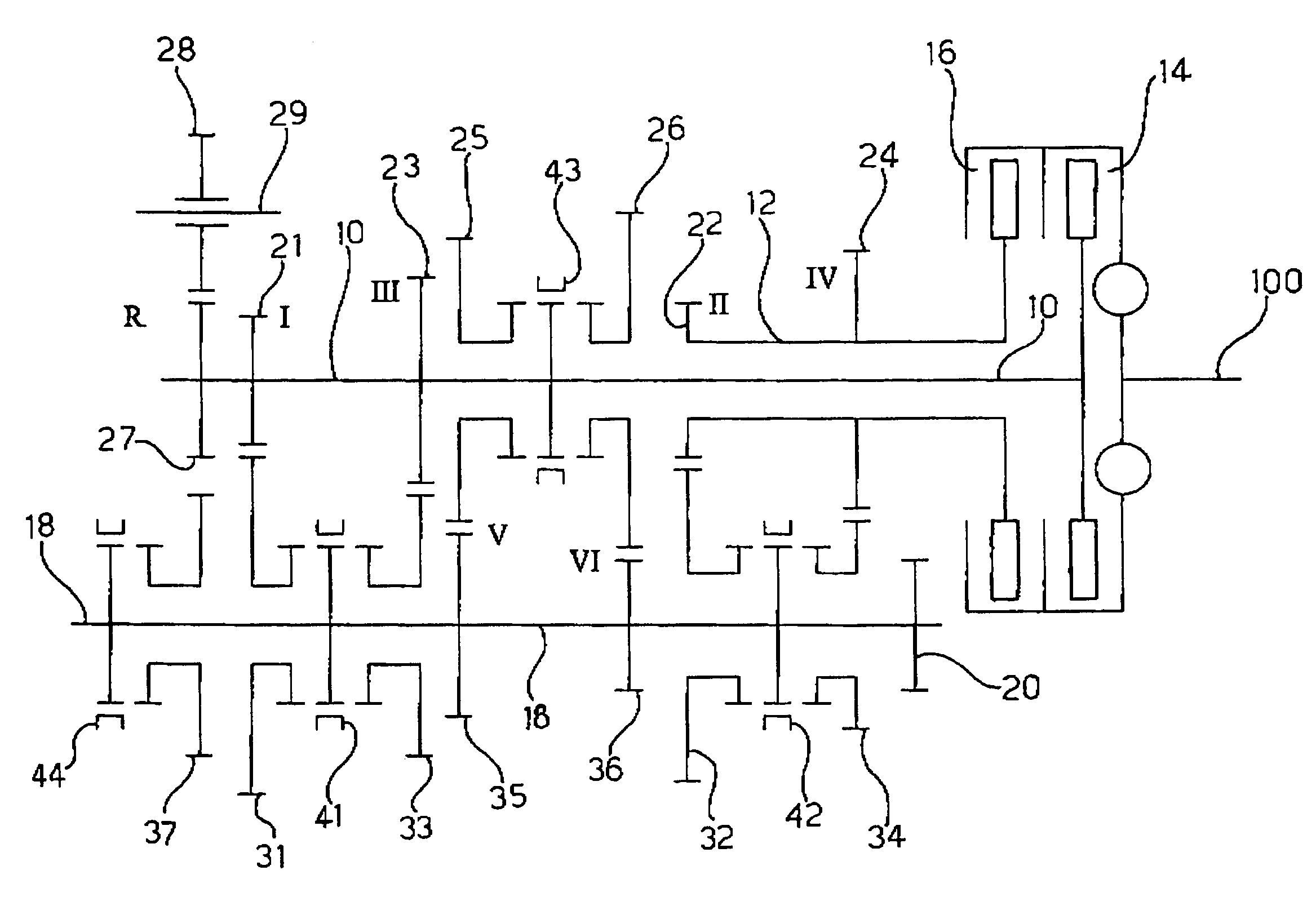
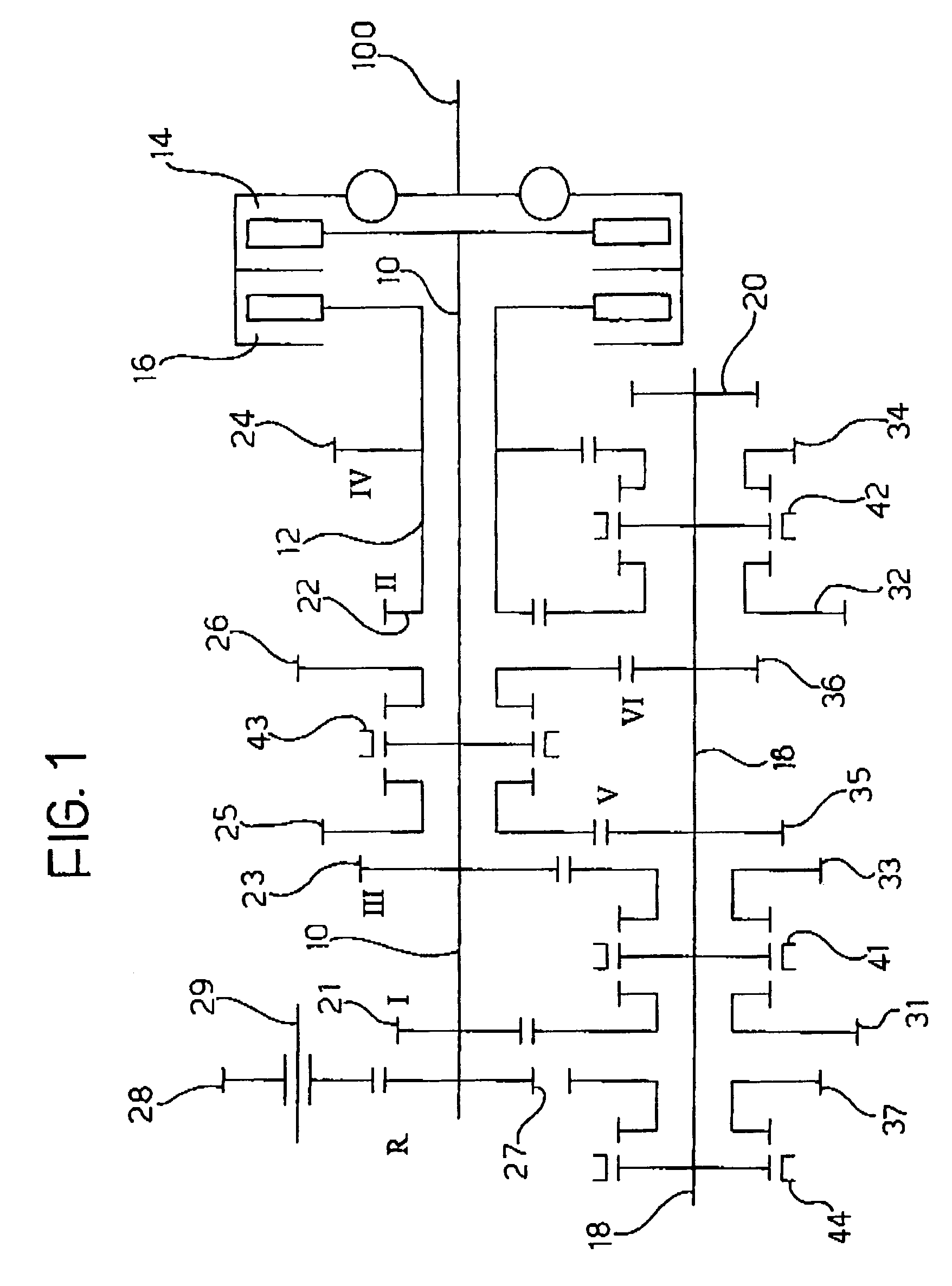
[0035]The gear sets relating to the first four forward gear ratios are arranged as in the

[0036]With regard, however, to fifth and sixth gears, the first input shaft 10 controls rotation of the drive gearwheel 25 of fifth gear and the drive gearwheel 26 of sixth gear, which mesh with the driven gearwheels 35 and 36 respectively, mounted idly on the second output shaft 17. The third coupling sleeve 43 is fitted between the two idle driven wheels 35 and 36 and is selectively movable either to left or right to engage the fifth and sixth gear respectively.

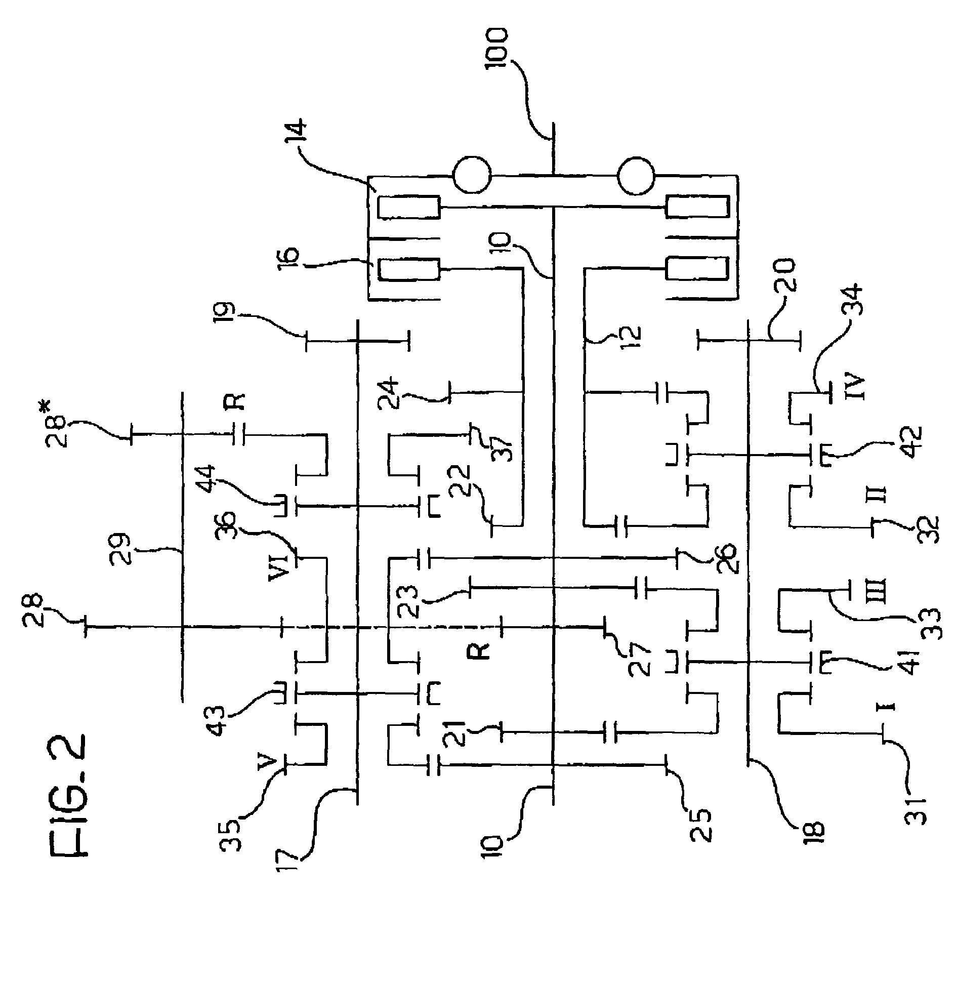
[0037]Finally, as for fifth and sixth gears, the driven gearwheel 37 of reverse gear is mounted idly on the second output shaft 17 and can be coupled for rotation with this shaft by means of the fourth coupling sleeve 44. In contrast to the first embodiment, the lay shaft 29 carries two gearwheels 28 and 28* which mesh with the reverse gear drive gearwheel 27 and the reverse gear driven gearwheel 37, respectively.

[0038]Obviously, the tw...

second embodiment

[0057]the transmission control system according to the invention is electro-mechanically operated. With reference to FIG. 8, the first control device 50 includes a first electric motor 86 for controlling rotation of the drum 54 (by means of a reduction gear 87, possibly provided with a damper device), while the second control device 52 includes a second electric motor 88 for controlling translation movement of the slidable rod 64 by means of a mechanism for reduction and conversion of rotary motion into linear motion, which includes a pinion 89 and a rack 90 and is possibly provided with a damper device. Alternatively, it is possible to provide a coaxial configuration of the motor 88 and the rod 64, by using a lead screw and nut motion conversion mechanism or a re-circulating-ball arrangement.

[0058]Two additional electro-mechanical actuators (not shown) are also provided for controlling the two clutches 14 and 16.

[0059]Both the control systems illustrated above, in combination with ...


PUM


Abstract

The transmission includes: a first input shaft carrying drive gearwheels for first gear, third gear, fifth gear, sixth gear and reverse; a second input shaft, coaxial to the first, carrying drive gearwheels for second gear and fourth gear; first and second clutches for coupling the first and the second input shafts respectively to a drive shaft of the motor vehicle; and at least one output shaft carrying a plurality of driven gearwheels, each meshing, either directly or indirectly, with a corresponding drive gearwheel; a first engagement sleeve associated with the drive gearwheels or driven gearwheels of first and third gears; a second engagement sleeve associated with the drive gearwheels or driven gearwheels of second and fourth gears; a third engagement sleeve associated with the drive gearwheels or driven gearwheels of fifth and sixth gears; and a fourth engagement sleeve associated with the drive gearwheel or driven gearwheel of reverse gear.

Description

BACKGROUND OF THE INVENTION[0001]The present invention relates to a double-clutch transmission architecture for a motor vehicle, having the characteristics specified in the preamble to claim 1.[0002]A six speed transmission architecture of the type indicated above is known, for example, from European Patent Application EP-A-1 245 863, in the name of the Applicant. According to this known arrangement, the transmission includes:[0003]first and second coaxial input shafts and at least one output shaft;[0004]first and second clutches operable to couple the first and second input shafts respectively to a drive shaft;[0005]a first set of drive gearwheels associated with the odd gear ratios (first, third and fifth) and with the reverse gear, carried on the first input shaft;[0006]a second set of drive gearwheels associated with the even gear ratios (second, fourth and sixth), carried by the second input shaft;[0007]a plurality of driven gearwheels associated with the various gear ratios of...

Claims


Application Information

Patent Timeline
Patent Type & Authority Patents(United States)
IPC IPC(8): F16H3/08F16H3/00F16H3/089F16H3/093F16H61/30F16H61/32F16H61/688F16H63/04F16H63/18
CPCF16H3/006F16H3/089F16H3/093F16H61/30F16H61/32Y10T74/19233F16H63/04F16H63/18F16H2003/0931F16H2200/0052F16H61/688
Inventor BALDASCINI, FILIPPOCAENAZZO, DARIOMESITI, DOMENICOPREGNOLATO, GIANLUIGI
Owner CENT RICERCHE FIAT SCPA
Why Eureka
Try Eureka