Suspension system for a vehicle with a tank for liquified gas

a suspension system and tank technology, applied in the field of rear suspension sub-assembly, can solve the problems of suspension design and structural difficulties, onboard vehicle storage of hydrogen gas or natural gas, and designers are restricted, so as to improve rigidity, maximize space, and enhance handling

Inactive Publication Date: 2007-04-03
THE JOHN HOPKINS UNIV SCHOOL OF MEDICINE
View PDF28 Cites 31 Cited by
  • Summary
  • Abstract
  • Description
  • Claims
  • Application Information

AI Technical Summary

Benefits of technology

[0012]There are two embodiments in the inventive suspension assembly (1) a semi-trailing design consisting of arms mounted to a forward crossmember that extend past the centerline of wheel assemblies to have their free ends connected by a stabilizing lateral link and (2) a wishbone design with arms that straddle the tank and attach to both a forward and aft crossmember. The two advantages of either embodiment of the inventive suspension subassembly is its improved rigidity for enhanced handling and maximizing the space between the rear wheels for a larger storage volume tank.
[0013]Wrapping the rear suspension subassembly around a single fuel tank allows the inventive assembly to efficiently carry a large volume of gas while minimizing the loss of space within the passenger compartment or trunk. The single large diameter fuel tank is the most cost, weight and volumetric efficient storage container for high-pressure gas. Attaching the tank to body of the vehicle as far away as reasonable from the rear bumper and surrounding it by the rear suspension affords high crashworthiness protection in case of a rear or side impact collision.
[0014]It is, therefore, an object of the present invention to provide a rear suspension subassembly with improved rigidity so as to hold the rear wheels of the vehicle in alignment under severe road conditions
[0015]Still another object of the invention is to provide a rear suspension assembly, which has a minimum structure between the wheel centerline to enable carrying a single large-diameter, long overall length gaseous storage tank, configured to maximize fuel volume.
[0016]Yet a further object of the invention is to provide an arrangement that allows for the onboard storage of a large volume tank while minimizing intrusion into the trunk compartment or passenger space and yet provide sufficient undercarriage ground clearance.
[0017]Yet a further object of this invention is to provide an arrangement that positions a large diameter, high-pressure gaseous fuel tank as far as possible from the rear of the vehicle for crashworthiness protection.

Problems solved by technology

The onboard vehicle storage of hydrogen gas or natural gas poses challenges in the areas of relatively low energy density, system cost, crashworthiness, and vehicle packaging.
Large cylinders however pose a problem for vehicle packaging, impacting vehicle interior space (passenger, trunk or truckbed), undercarriage clearance and / or room for suspension assemblies that provide handling and ride acceptable to drivers.
However, the designer is constrained by mechanical conflicts between structural members, and fuel storage containers that also must fit into the vehicle.
A large-volume gaseous fuel tank, mounted between the rear wheels provides suspension design and structural difficulties.
As a result, the rear suspension may not be sufficiently stiff to keep the rear wheels aligned, which leads to the vehicle's lateral instability, particularly when it is driven on rough terrain.
This structure may not be rigid enough to provide stiffness sufficient to keep the rear wheels aligned.
Misalignment of the rear wheels leading to the lateral instability of the car renders the ride both unpleasant and unsafe.
In addition stabilizing arms aligned with the principal axis of the storage tank and the wheel occupy valuable space in the undercarriage that reduces the overall tank length and thus the volume of gaseous fuel that can be carried onboard.

Method used


Image

  • Suspension system for a vehicle with a tank for liquified gas
  • Suspension system for a vehicle with a tank for liquified gas
  • Suspension system for a vehicle with a tank for liquified gas

Examples


Embodiment Construction

[0025]A preferred embodiment of the present invention will be described herein below with reference to the accompanying drawings. In the following description, well-known functions or constructions are not described in detail since they would obscure the invention in unnecessary detail.

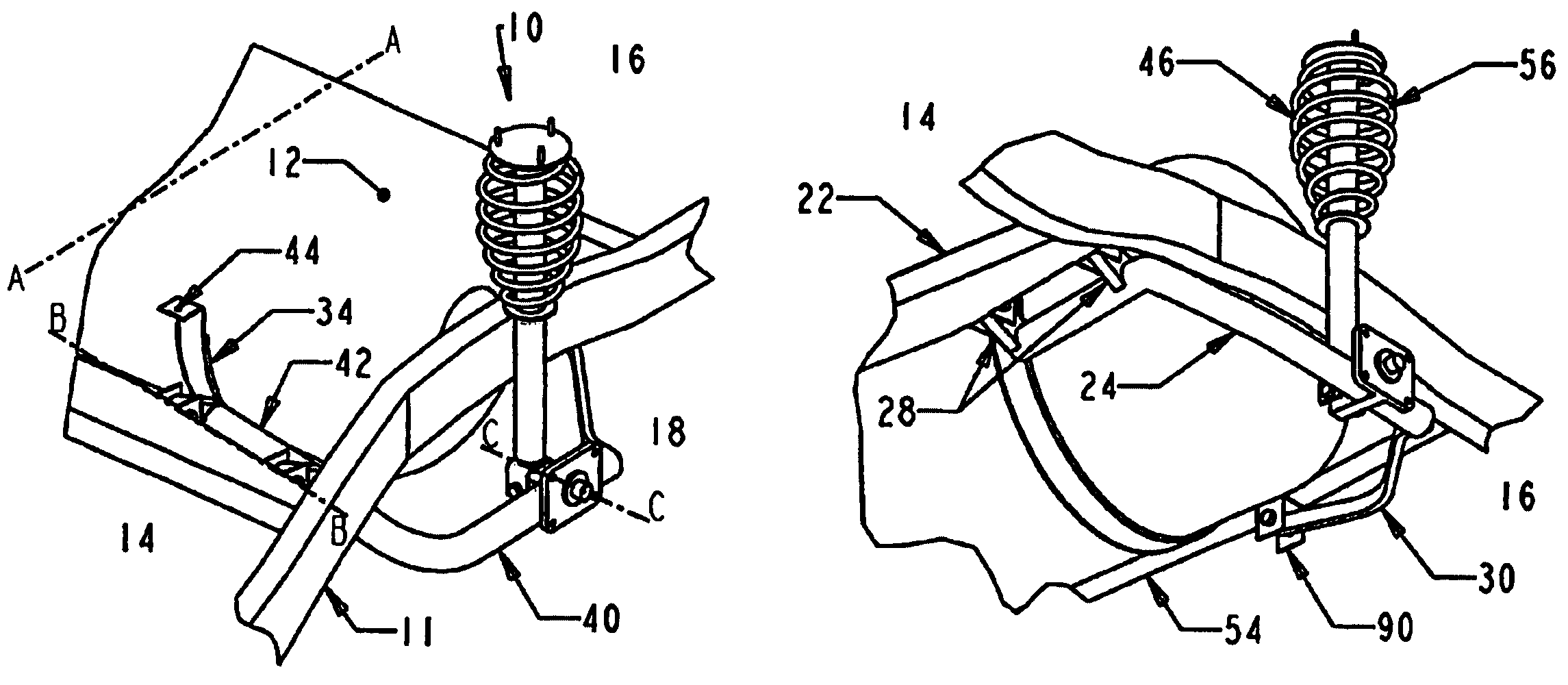
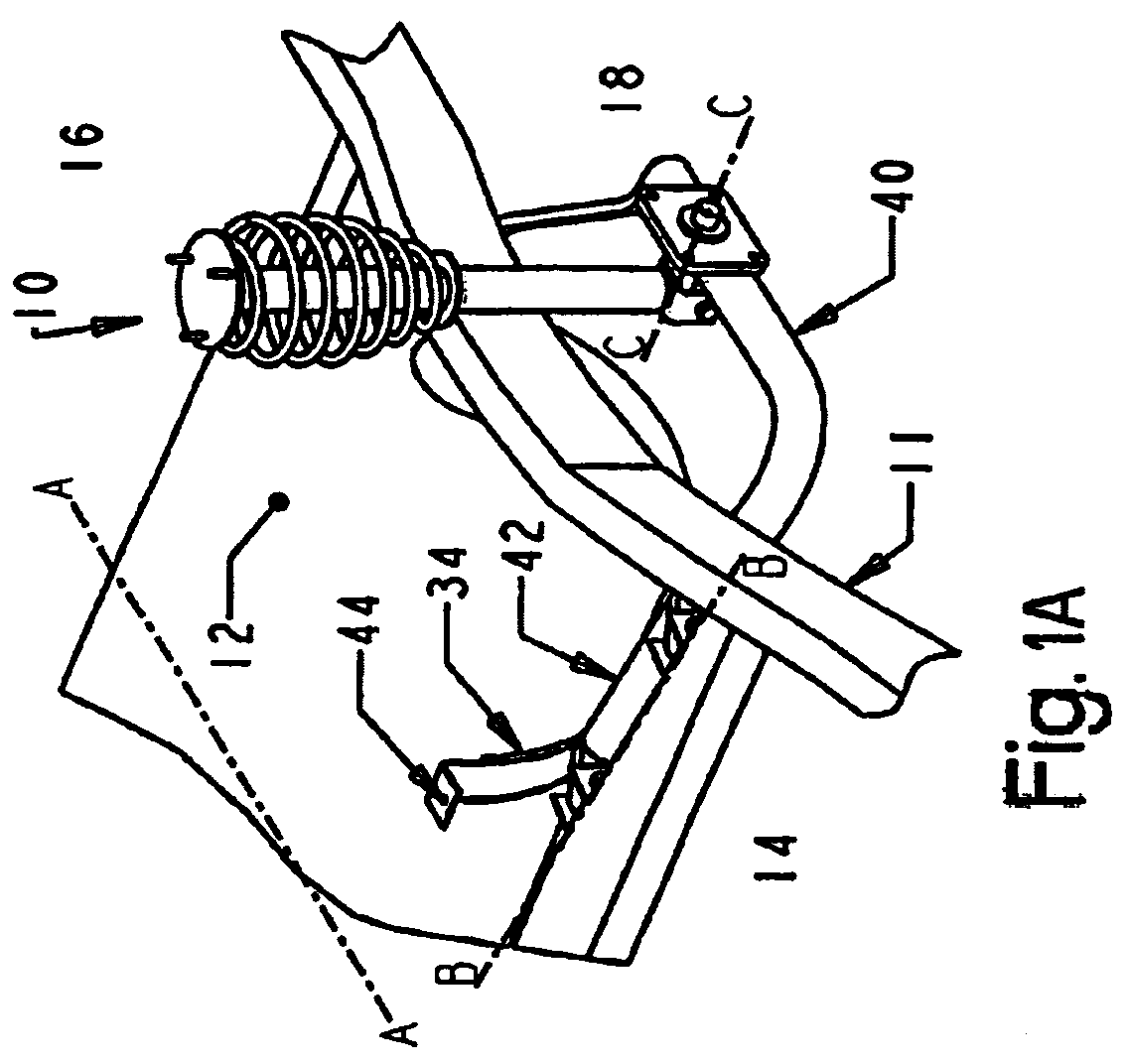
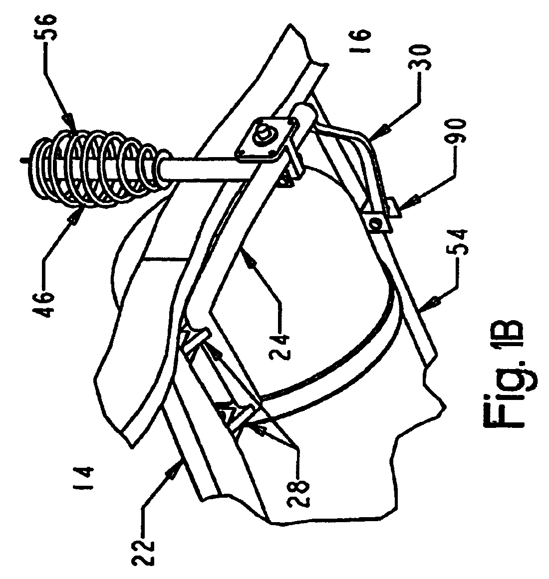
[0026]Referring to FIGS. 1–5, a rear-suspension assembly for the chassis 10 (FIGS. 1A, 1B, 2A and 2B) of a vehicle powered by a combustion engine or a fuel cell is configured to conform to a contour of a single, lightweight, all-composite gaseous storage tank 12. The inventive configuration of the inventive suspension assembly designs, i.e., a trailing arm design, as illustrated in FIGS. 1A–1B, and a wishbone design, as seen in FIGS. 2A–2B, allows both front 14 and rear 16 (FIG. 2) portions of the vehicle to contribute to the overall rigidity of the suspension, particularly to a rear suspension subassembly 18. As a consequence of enhanced rigidity, the rear suspension subassembly 18 exhibits the impro...


PUM


Abstract

A suspension system for carrying a compressed gas fuels in vehicle. The suspensions arms and springs are configured to maximize the space between the wheels while providing a high degree of suspension stiffness to maintain proper wheel alignment during cornering, braking and in rough terrain. The suspension arms have two broadly-spaced attachment points to the chassis that provides structural rigidity to the rear suspension subassembly.

Description

CROSS-REFERENCE TO RELATED APPLICATION[0001]This application claims priority to U.S. Provisional Application No. 60 / 332,836 filed on Nov. 6, 2001, the contents of which are incorporated by reference herein.BACKGROUND OF THE INVENTION[0002]1. Field of the Invention[0003]The present invention relates to a method and system for the onboard storage of a large volume of high-pressure hydrogen or natural gas on vehicles powered by either internal combustion engines or fuel cells. Particularly, this invention relates to a rear suspension subassembly having improved structural rigidity, that is designed to straddle a large diameter high-pressure storage tank with high volumetric efficiency.[0004]2. Description of the Relation Art[0005]Hydrogen powered Fuel Cell Vehicles (FCV) and natural gas powered vehicles are solution to problems of air quality and dependency on petroleum fuel. Fuel cells produce electricity by combining hydrogen with oxygen from air to produce electrical power and give ...

Claims


Application Information

Patent Timeline
Patent Type & Authority Patents(United States)
IPC IPC(8): B60P3/22B60G3/06B60G3/14B60G7/00B60G21/02B60G21/055B60K15/03B60K15/07
CPCB60G3/06B60G3/14B60G7/001B60G21/026B60G21/0551B60K15/03006B60K15/07B60G2200/13B60G2200/132B60G2200/14B60G2200/142B60G2204/143B60G2204/20B60G2206/012B60G2206/122B60G2206/124B60G2206/604
Inventor WOZNIAK, JOHN J.HILDEBRAND, RICHARD J.
Owner THE JOHN HOPKINS UNIV SCHOOL OF MEDICINE
Why Eureka
Try Eureka