Glazing

a technology of glazing panels and coatings, applied in the field of glazing panels, can solve the problems of causing an increase in the tl of the glazing panel, and achieve the effects of enhancing the properties of the coating stack, preventing significant contamination and/or diffusion, and enhancing mechanical properties

Inactive Publication Date: 2007-04-03
GLAVERBEL SA
View PDF17 Cites 31 Cited by
  • Summary
  • Abstract
  • Description
  • Claims
  • Application Information

AI Technical Summary

Benefits of technology

[0014]The base antireflective upper layer and / or the central antireflective upper layer may have a geometrical thickness of less than about 200 Å, less than about 150 Å, less than about 130 Å or less than about 110 Å. This may provide advantageous mechanical properties to the coating stack, particularly with respect to resistance to peel tests.
[0015]The base antireflective upper layer and / or the central antireflective upper layer may have a geometrical thickness of greater than about 30 Å, greater than about 50 Å greater than about 100 Å. This may provide a sufficient thickness to enhance the properties of the coating stack, particularly with respect to TL obtainable after heat treatment.
[0016]The central antireflective lower layer may comprises at least one layer which provides a sufficient block to the migration of oxygen and / or sodium and / or other materials to prevent significant contamination of and / or diffusion of the layers of the coating stack. Preferably, the central antireflective lower layer is in direct contact with the first barrier layer and comprises a material which resists diffusion of the first barrier layer during heat treatment. The combination of a central antireflective lower layer with a first barrier which is deposited at least partially in metallic or substantially metallic form and subsequently oxidised during heat treatment (and particularly a barrier that comprises or consists essentially of metallic Ti when deposited) may permit particularly high thermal stability of the coating stack during heat treatment. It is believed that diffusion of material from the first baffler layer into the central antireflective lower layer during heat treatment and particularly during severe heat treatment may, in some coating stack arrangements be a critical factor in determining thermal stability of the coating stack; the composition of the central antireflective lower layer may significantly mitigate against such diffusion.
[0017]The base antireflective lower layer may comprise at least one layer which provides a sufficient block to the migration of oxygen and / or sodium and / or other materials to prevent significant contamination of and / or diffusion of the layers of the coating stack. The use of a base antireflective lower layer may be used to facilitate this whilst, in addition, facilitating the arrangement and control of the deposition conditions.
[0018]The use of a top antireflective layer may facilitate the arrangement and control of the deposition conditions for the overall coating stack. In addition, this layer may be arranged to provide a black to migration of oxygen during heat treatment and / or diffusion of the second barrier layer.
[0019]The top antireflective layer may comprise at least one layer which comprises a mixed oxide of Zn and at least one additional material W, in which the ratio W / Zn in that layer is between 0.02 and 0.5 by weight and in which W is one or more of the materials selected from the group comprising Sn, Al, Ga, In, Zr, Sb, Bi, Mg, Nb, Ta and Ti. This may improve the thermal stability of the coating stack during heat treatment and / or its mechanical or chemical resistance.

Problems solved by technology

This oxidation of the barrier during heat treatment provokes an increase in TL of the glazing panel.

Method used


Image

  • Glazing
  • Glazing

Examples


example 1

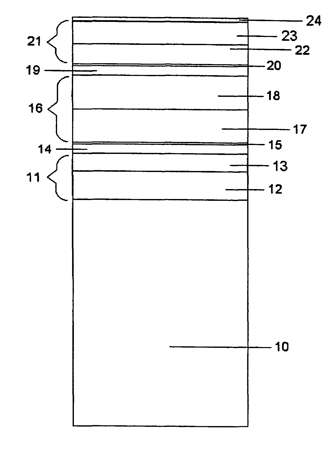
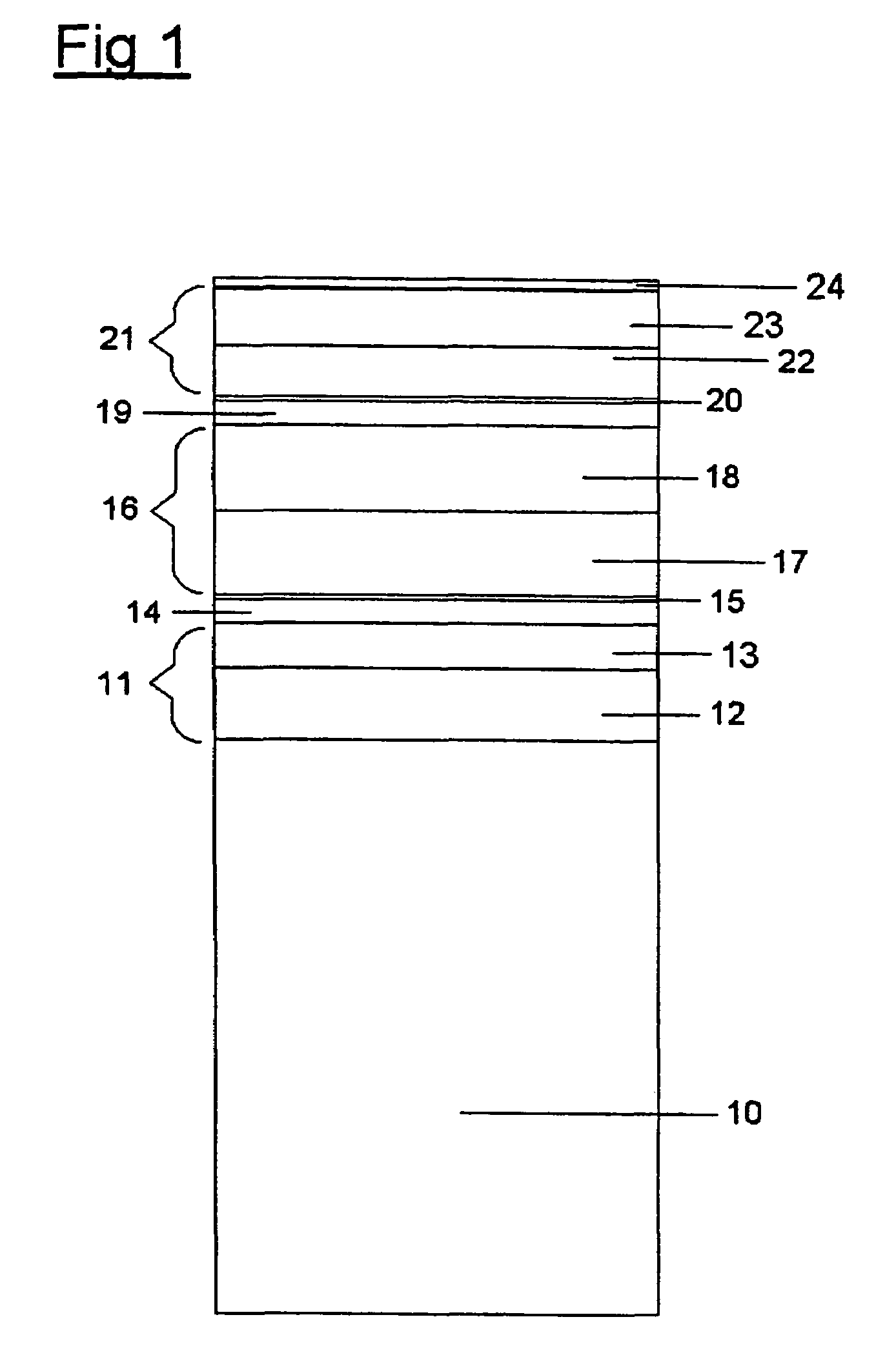
[0046]FIG. 1 shows a double Ag layer, heat treatable, coating layer deposited on a substantially flat or planar glass substrate by magnetron sputtering and having the following sequential structure:

[0047]

ReferenceGeometricalratio of Sn / Znnumberthicknessby weightGlass substrate10    2 mmBase antireflective layer11comprising:lower layer of ZnSnOx12200 Å0.7upper layer of ZnSnOx13100 Å0.17Ag14100 ÅTi overlying barrier15 40 ÅCentral antireflective layer16comprisingcentral lower layer of ZnSnOx17650 Å0.7upper layer of ZnSnOx18100 Å0.17Ag19100 ÅTi overlying barrier20 40 ÅTop antireflective layer21comprising:lower layer of ZnSnOx22 80 Å0.17upper layer of ZnSnOx23140 Å0.7protective overcoat of Ti24 30 Å

[0048]in which ZnSnOx is a mixed oxide containing Zn and Sn deposited in this example by reactively sputtering a target which is an alloy or mixture of Zn and Sn in the presence of oxygen.

[0049]Alternatively, a mixed oxide layer may be formed by sputtering a target which is a mixture of zinc o...


PUM

PropertyMeasurementUnit
luminous transmittanceaaaaaaaaaa
temperatureaaaaaaaaaa

Abstract

A glazing panel comprises in sequence at least a glass substrate, a base antireflective layer comprising at least a base antireflective lower layer and a base antireflective upper layer which is of a different composition to that of the base antireflective lower layer, the base antireflective upper layer comprising a mixed oxide of Zn and at least one additional material X, in which the ratio X/Zn in the base antireflective upper layer is between 0.02 and 0.5 by weight and in which X is one or more of the materials selected from the group comprising Sn, Al Ga, In, Zr, Sb, Bi, Mg, Nb, Ta and Ti, a first infra-red reflecting layer, a first barrier layer, a central antireflective layer comprising at least a central antireflective lower layer and a central antireflective upper layer which is of a different composition to that of the central antireflective lower layer, the central antireflective lower layer being in direct contact with the first barrier layer and the central antireflective upper layer comprising a mixed oxide of Zn and at least one additional material Y, in which the ratio Y/Zn in the base antireflective upper layer is between 0.02 and 0.5 by weight and in which Y is one or more of the materials selected from the group comprising Sn, Al, Ga, In, Zr, Sb, Bi, Mg, Nb, Ta and Ti, a second infra-red reflecting layer, a second barrier layer, a top antireflective layer. The coating stack of such a glazing panel may provide particularity advantageous levels of the thermal stability so as to facilitate heat treatment of the glazing panel.

Description

CROSS-REFERENCE TO RELATED APPLICATIONS[0001]This application is a continuation of U.S. application Ser. No. 10 / 110,461, having a U.S. “filing date” of 24 May, 2002, now U.S. Pat. No. 6,797,389 which was the entry into the U.S. National Stage of PCT Application No. PCT / EP00 / 10278 filed 13 Oct. 2000, and which claims priority from European Application No. 99203357.1 filed 14 Oct. 1999, the disclosures of all of which are hereby incorporated by reference.BACKGROUND OF THE INVENTION[0002]This invention relates to glazing panels and particularly to glazing panels which are intended to undergo heat treatment following application of a solar control filter.[0003]EP 233003A describes a glazing panel carrying a sputter coated optical filter having the structure: glass substrate / SnO2 base dielectric / first metallic barrier of Al, Ti, Zn, Zr or Ta / Ag / second metallic barrier of Al, Ti, Zn, Zr or Ta / SnO2 top dielectric. The optical filter is designed to block a significant portion of the inciden...

Claims


Application Information

Patent Timeline
Patent Type & Authority Patents(United States)
IPC IPC(8): B32B17/06B32B17/10C03C17/36
CPCB32B17/10036B32B17/10174B32B17/10339B32B17/10761C03C17/36C03C17/3618C03C17/3644C03C17/3652C03C17/366C03C17/3681C03C17/3639Y10T428/24942C03C2217/73
Inventor DEPAUW, JEAN-MICHEL
Owner GLAVERBEL SA
Why Eureka
Try Eureka