Tunable multimode wavelength division multiplex Raman pump and amplifier, and a system, method, and computer program product for controlling tunable Raman pumps, and Raman amplifiers

Active Publication Date: 2007-04-03
OPLINK TECH INC
View PDF27 Cites 14 Cited by
  • Summary
  • Abstract
  • Description
  • Claims
  • Application Information

AI Technical Summary

Benefits of technology

[0031]The inventors of the present invention have recognized that conventional optical communication systems are limited as to their flexibility and adaptability. Accordingly, one object of the present invention is to provide a tunable multimode wavelength division multiplex Raman pump and amplifier, and a system, method and computer program product for controlling the same, which address the above-identified and other limitations of conventional systems. The present inventors have recognized that conventional Raman amplifiers are manufactured to meet a customer's needs and are not able to adapt to changes in a customer's requirements, or to sub-optimal performance based on, for example, temperature variations. To the contrary, as requirements change, components such as Raman amplifiers are replaced with components that are manufactured to accommodate those new requirements. Accordingly, another object of the present invention is to provide a tunable Raman amplifier that uses tunable semiconductor laser devices that include integrated diffraction gratings. By providing a tunable Raman amplifier, more flexible optical communication systems can be built that can be controlled to adjust to either changes in the requirements of the network, or to sub-optimal performance caused by a variety factors. As an added benefit, the inventive Raman amplifier will not need to use fiber Bragg gratings external to the semiconductor laser device, which allow for the introduction of noise and losses into the system, as discussed above.
[0032]To achieve these and other objects, the present invention provides a novel tunable multimode WDM Raman amplifier, control system, method and software that uses a plurality of pumps, whose optical outputs and central wavelengths are controlled by a control unit. Controlling both the wavelength and optical output of the pumps to predetermined levels and / or wavelengths enables a flexible approach toward Raman amplifying a WDM optical signal that propagates through the optical fiber that serves as the Raman gain medium. The control unit ensures that the Raman amplification profile (e.g., a predetermined amplifier gain profile across the amplification bandwidth, and / or the amplification wavelength span) is set and maintained to be consistent with system requirements.
[0035]Another feature of the present invention is that each Raman amplifier in an optical communication system need not operate alone, but rather may operate in an internetworked fashion with other amplifiers in the system. Since Raman amplification is a distributed amplification, the present invention exploits this distributed effect by shifting amplification duties between adjacent, cascaded Raman amplifiers so as to compensate for unforeseen changes in component operations or system requirements.
[0037]Another feature of the present invention is to provide a narrow band amplifier that is able to flexibly apply, over a wide wavelength range, multi-mode pumping light having a predetermined pumping bandwidth to different portions of a spectrum, within a 100 nanometer wavelength tuning range of the tunable LD module.

Problems solved by technology

The present inventors have recognized that conventional Raman amplifiers are manufactured to meet a customer's needs and are not able to adapt to changes in a customer's requirements, or to sub-optimal performance based on, for example, temperature variations.

Method used


Image

  • Tunable multimode wavelength division multiplex Raman pump and amplifier, and a system, method, and computer program product for controlling tunable Raman pumps, and Raman amplifiers
  • Tunable multimode wavelength division multiplex Raman pump and amplifier, and a system, method, and computer program product for controlling tunable Raman pumps, and Raman amplifiers
  • Tunable multimode wavelength division multiplex Raman pump and amplifier, and a system, method, and computer program product for controlling tunable Raman pumps, and Raman amplifiers

Examples


Embodiment Construction

,” and more generally throughout the entire document.

BRIEF DESCRIPTION OF THE DRAWINGS

[0042]A more complete appreciation of the present invention and many of the attendant advantages thereof will be readily obtained as the same becomes better understood by reference to the following detailed description when considered in connection with the accompanying drawings, wherein:

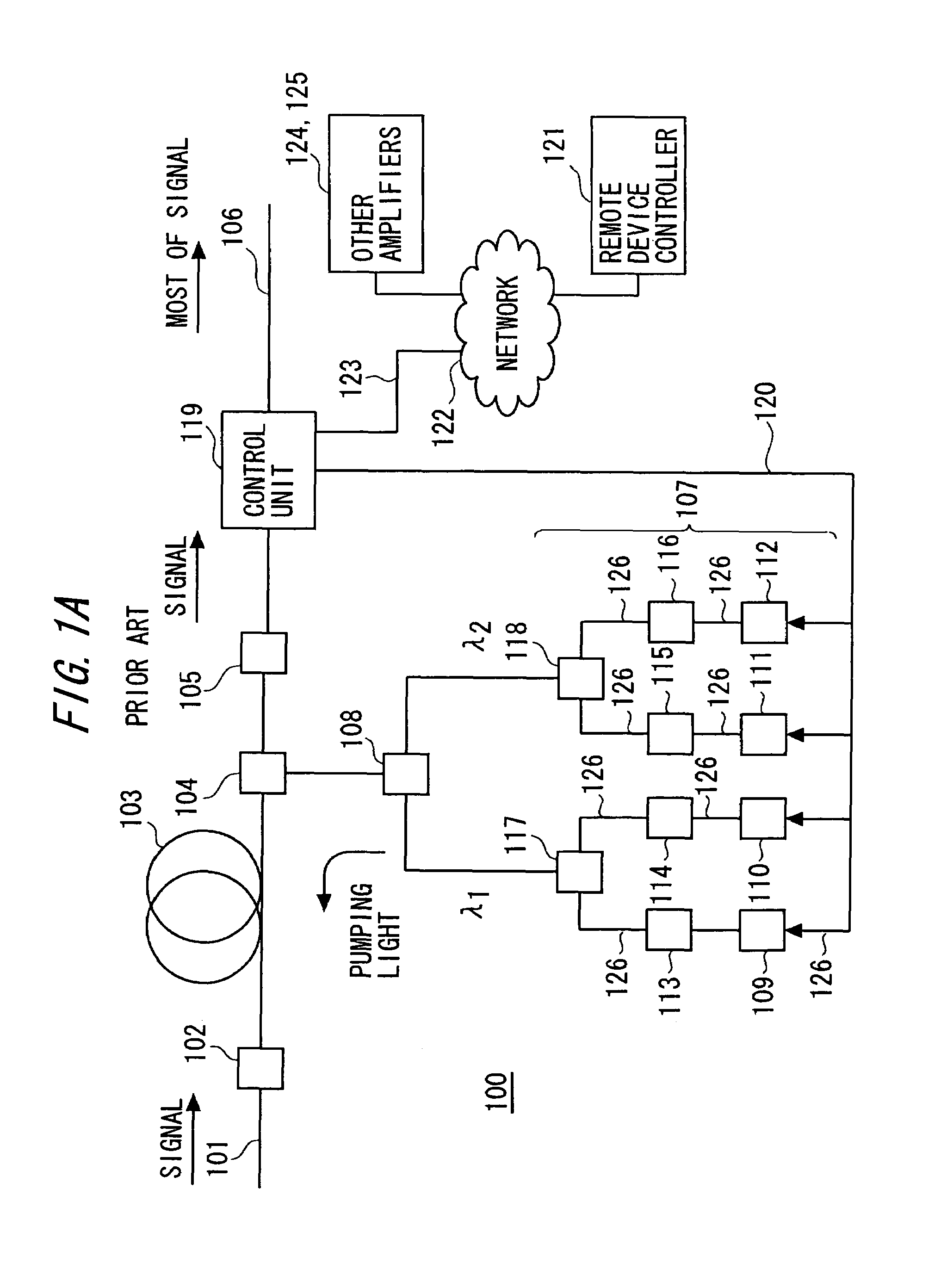
[0043]FIG. 1A is a block diagram illustrating a conventional Raman amplifier;

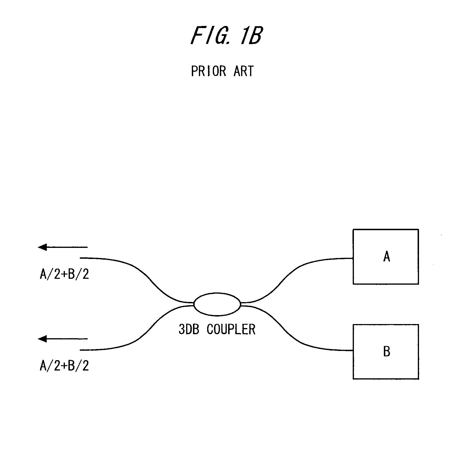
[0044]FIG. 1B is a block diagram of a conventional redundant pump source for a Raman amplifier;

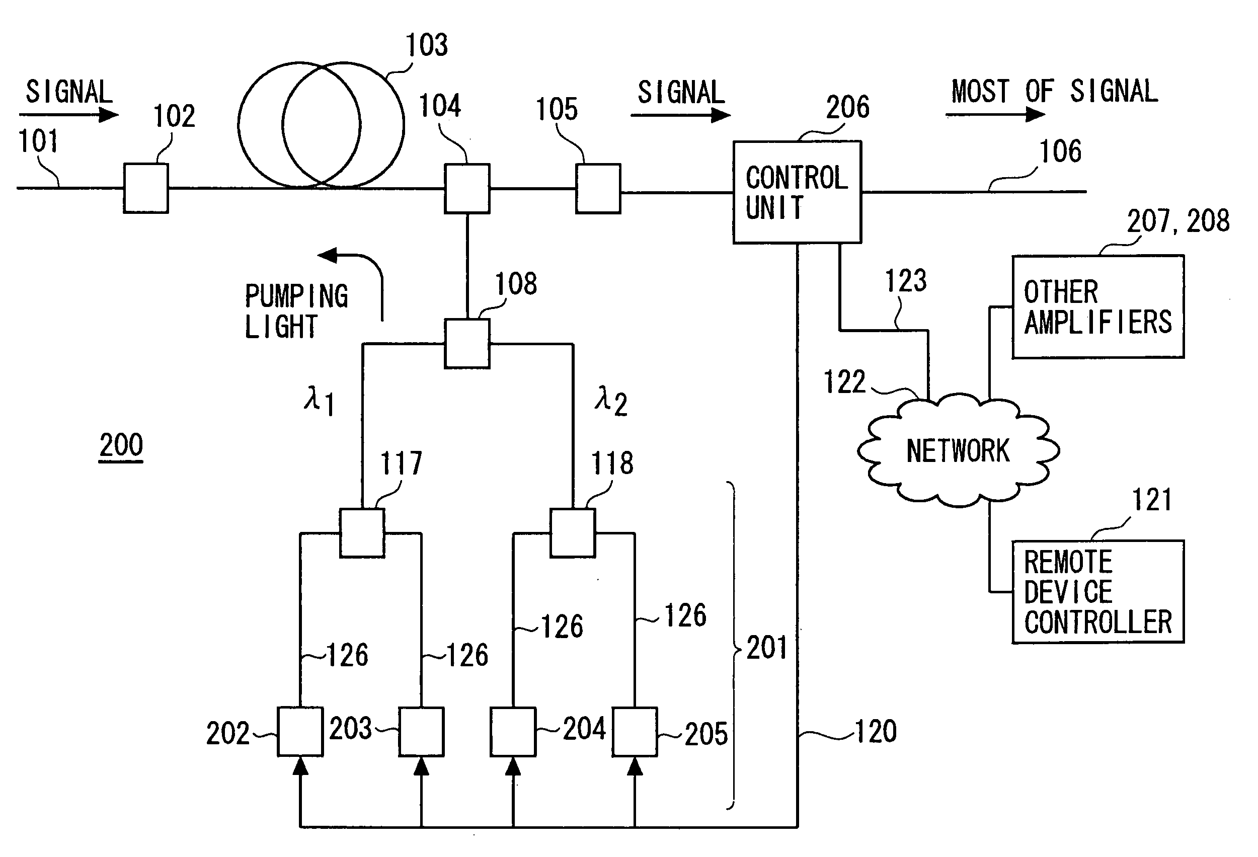
[0045]FIG. 2 is a block diagram illustrating a Raman amplifier according to one embodiment of the present invention;

[0046]FIG. 3 is a block diagram illustrating the details of the control unit for a Raman amplifier according to one embodiment of the present invention;

[0047]FIG. 4 is a schematic illustrating components included in the control unit according to the present invention;

[0048]FIG. 5 is a schematic illustrating other components included...


PUM


Abstract

A tunable multimode wavelength division multiplex Raman pump and amplifier, and a system, method, and computer program product for controlling a tunable Raman pump and amplifier. The tunability of the pump source is accomplished by controlling the optical output and central wavelengths of tunable semiconductor laser devices. The system includes a microprocessor-based controller that monitors an amplifier's performance and adjusts the drive current and / or wavelength of the tunable pumps of an amplifier to achieve a target performance.

Description

CROSS-REFERENCE TO RELATED PATENT APPLICATIONS[0001]This application claims the benefit of the earlier filing date of commonly owned U.S. provisional patent application Ser. No. 60 / 364,127 filed on Mar. 15, 2002, entitled A TUNABLE MULTIMODE WAVELENGTH DIVISION MULTIPLEX RAMAN PUMP AND AMPLIFIER, AND A SYSTEM, METHOD, AND COMPUTER PROGRAM PRODUCT FOR CONTROLLING TUNABLE RAMAN PUMPS, AND RAMAN AMPLIFIERS; and provisional patent application Ser. No. 60 / 364,034 filed Mar. 15, 2002, entitled DEVICE AND METHOD FOR PROVIDING A TUNABLE SEMICONDUCTOR LASER, the entire contents of each of which, including all appendices contained therein, being incorporated herein by reference. This application also contains subject matter related to that disclosed in U.S. Pat. No. 6,292,288, filed on Mar. 17, 2000, entitled “RAMAN AMPLIFIER, OPTICAL REPEATER, AND RAMAN AMPLIFICATION METHOD”; U.S. patent application Ser. No. 09 / 832,885, filed on Apr. 12, 2001, entitled “SEMICONDUCTOR LASER DEVICE FOR USE IN ...

Claims


Application Information

Patent Timeline
IPC IPC(8): H01S4/00H04B10/12H01S3/00H01S3/131H01S3/30
CPCH01S3/131H01S3/302H01S3/09408H01S3/094096H01S3/10069H01S3/1022H01S2301/04
Inventor EMORI, YOSHIHIRONAMIKI, SHUYOSHIDA, JUNJITSUKIJI, NAOKI
Owner OPLINK TECH INC
Why Eureka
Try Eureka