
Multiple reuse patterns for channels of wireless networks

a wireless network and channel technology, applied in the direction of network planning, electrical equipment, selection arrangements, etc., can solve the problems of reducing the capacity of the system, and the restriction of the frequency allocation of the base station in these systems, so as to achieve greater capacity, cost-effective, and reliable or flexible

Active Publication Date: 2007-04-03
MALIKIE INNOVATIONS LTD
View PDF20 Cites 24 Cited by
  • Summary
  • Abstract
  • Description
  • Claims
  • Application Information

AI Technical Summary

Benefits of technology

The present invention provides improved apparatus and methods for a wireless network having multiple channels for communication between base stations and user equipments. The base station has an allocator that favors allocation of a channel from one of two complementary patterns for areas of low carrier to interference ratio C / I, which helps avoid reducing the sacrifice of capacity or coverage in the tail of the C / I distribution. The reuse patterns are designed to maximize the use of available capacity and improve spatial coverage. The invention also allows for adapting the modulation and coding of the channels to alter data rate, and provides flexibility in selecting the most suitable pattern for a given user equipment. The invention can be applied to various types of wireless networks and can be upgraded in existing equipment. The technical effects of the invention include improved network performance and better user experience.

Problems solved by technology

Such arrangements are a particular problem in FWA (fixed wireless access) networks where subscribers have high gain narrow beamed directional antennas, because the directional antenna is still aligned with co-frequency sectors in adjacent (first pattern repeat) and more distant (second, third .
However the high frequency re-use factors typical in mobile systems reduces the capacity of the system in that less frequencies are available per base.
The allocation of frequencies to base stations in these systems is therefore typically restricted to prevent strong unwanted interfering signals from first pattern repeat cells.

Method used


Image

  • Multiple reuse patterns for channels of wireless networks
  • Multiple reuse patterns for channels of wireless networks
  • Multiple reuse patterns for channels of wireless networks

Examples


Embodiment Construction

FIG. 1. Elements of a Wireless Network

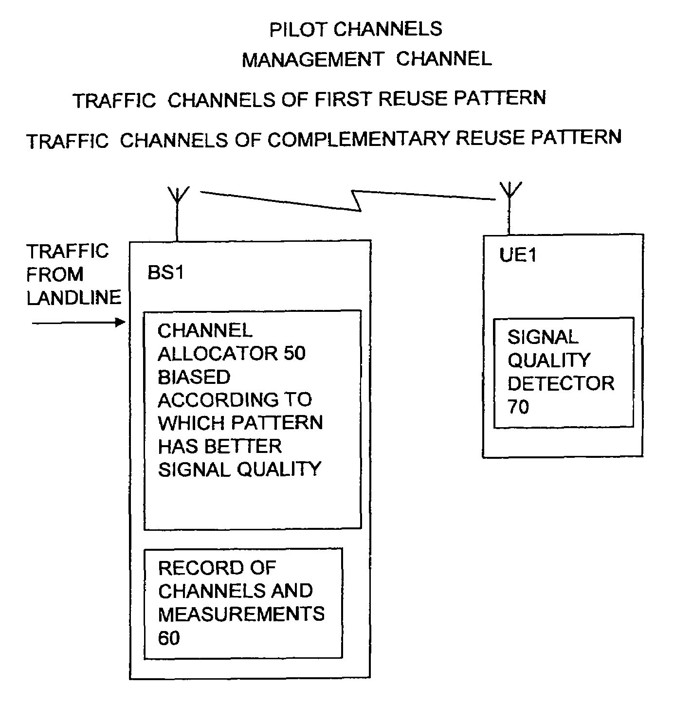
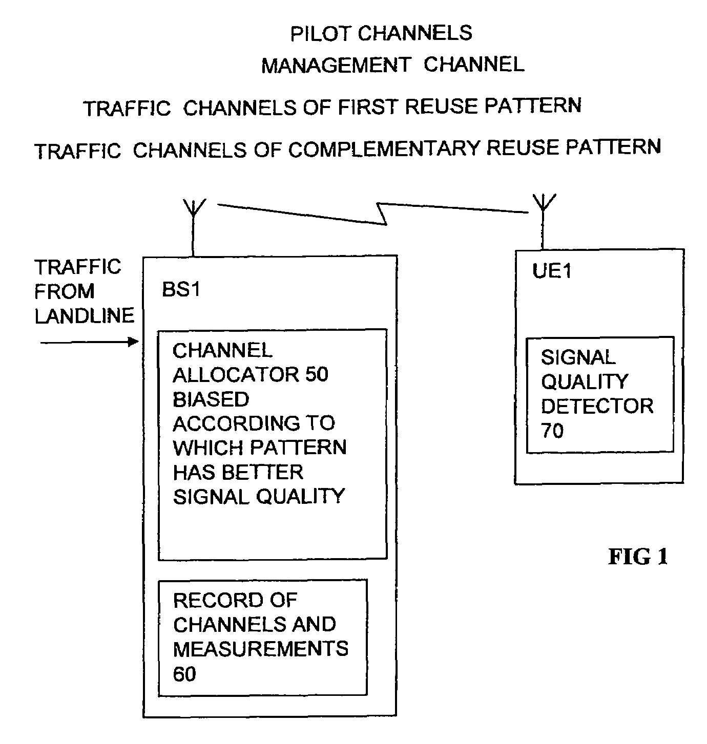
[0050]In FIG. 1, elements of a wireless network are shown. A base station BS1 and a user equipment UE1 are shown coupled by a number of wireless channels. There may be many base stations and many user equipments. For the sake of clarity only selected parts of the elements are illustrated. The base station includes channel allocator 50 for allocating particular traffic channels to each of the UEs. The operation of the base station is explained in more detail with reference to FIGS. 2 and 3 below. The wireless channels typically include pilot channels for use in measuring signal quality, management channels for exchanging information about the allocations, and other management information. Most of the band width is used by traffic channels. These can be frequencies, time slots or CDMA codes following established principles. The traffic channels have reuse patterns by sector or base station as will be explained below with reference to FIGS. 6 to 19...


PUM


Abstract

A base station for a wireless network has multiple channels for communicating with user equipments, and has multiple channel reuse patterns. The patterns are complementary such that areas of low carrier to interference ratio C / I of one pattern are not coincident with areas of low C / I of other patterns. An allocator allocates channels such that for user equipment located in an area of low C / I of any of the complementary patterns, the allocator favors allocation of a channel of another of the complementary patterns. The sacrifice of capacity can be reduced as there is less need for a capacity-hungry high re-use factor pattern. The channels may be frequencies, time slots or CDMA codes. The reuse patterns can involve reuse on selected base stations, or on selected sectors, or different polarizations. The network can be of any type including fixed wireless access FWA, or mobile networks.

Description

FIELD OF THE INVENTION[0001]This invention relates to base stations for wireless networks having multiple reuse patterns of channels, to networks having such base stations, to allocators for such networks, to methods of allocating channels to users, and to methods of offering a transmission service over such networks.BACKGROUND TO THE INVENTION[0002]Cellular communications networks are well known for both mobile and fixed subscribers. In cellular networks the coverage area is divided into cells, each cell is served by a base station or base site which allocates a frequency or group of frequencies which define communication channels between the subscriber and base station. The number of frequencies available to a cellular network is limited; so the frequencies are re-used over different cells to make maximum use of these frequencies while at the same time maintaining an acceptable level of interference between neighboring cells operating on the same frequency. Cells can be divided in...

Claims


Application Information

Patent Timeline
Patent Type & Authority Patents(United States)
IPC IPC(8): H04Q7/20H04W16/02H04W72/06
CPCH04W72/06H04W16/02H04W72/563
Inventor SMITH, MARTINWILSON, KEITH SROBSON, JULIUSWATKINS, MARK
Owner MALIKIE INNOVATIONS LTD
Learn More