Method and device for operating an internal combustion engine of a vehicle

Inactive Publication Date: 2007-04-10
ROBERT BOSCH GMBH
View PDF5 Cites 2 Cited by
  • Summary
  • Abstract
  • Description
  • Claims
  • Application Information

AI Technical Summary

Benefits of technology

[0005]With the exemplary method and / or exemplary device of the present invention, a derivative-action signal for adjusting an output variable to be output by the internal combustion engine is generated as a function of a steering operation (action). In this manner, the required reserve necessary for generating a constant propulsive torque at a constant accelerator position may even be generated in the case of a rapid, positive change in the assumed load (power consumption) due to the steering device. Therefore, the riding comfort is increased in this manner.
[0006]When the derivative-action signal is generated as a function of the steering-wheel angle acceleration (steering-angle acceleration). In this manner, the dynamics of a change in the load-circuit demand (power demand) of the steering device may be taken into account in a particularly simple and exact manner for generating the derivative-action signal.
[0008]When the derivative-action signal is generated as a function of a steering angle, the dependence of the dynamic change in the power consumption of the steering device on the position of the steering device may be taken into account when generating the reserve, so that the reserve may be adapted even more accurately to the dynamic change in the power consumption of the steering device, and the ride comfort is further increased.
[0010]When the derivative-action signal is reduced with decreasing steering angle, a reserve is also not necessary in this case, in which the power demand of the steering device is reduced.

Problems solved by technology

If the internal combustion engine of the engine is in an efficiency-optimized or exhaust-optimized operation, then it may not be possible to rapidly increase the oxygen or fuel concentration in the combustion chamber because of the inertia of the components used in the air system or fuel system.

Method used


Image

  • Method and device for operating an internal combustion engine of a vehicle
  • Method and device for operating an internal combustion engine of a vehicle
  • Method and device for operating an internal combustion engine of a vehicle

Examples


Embodiment Construction

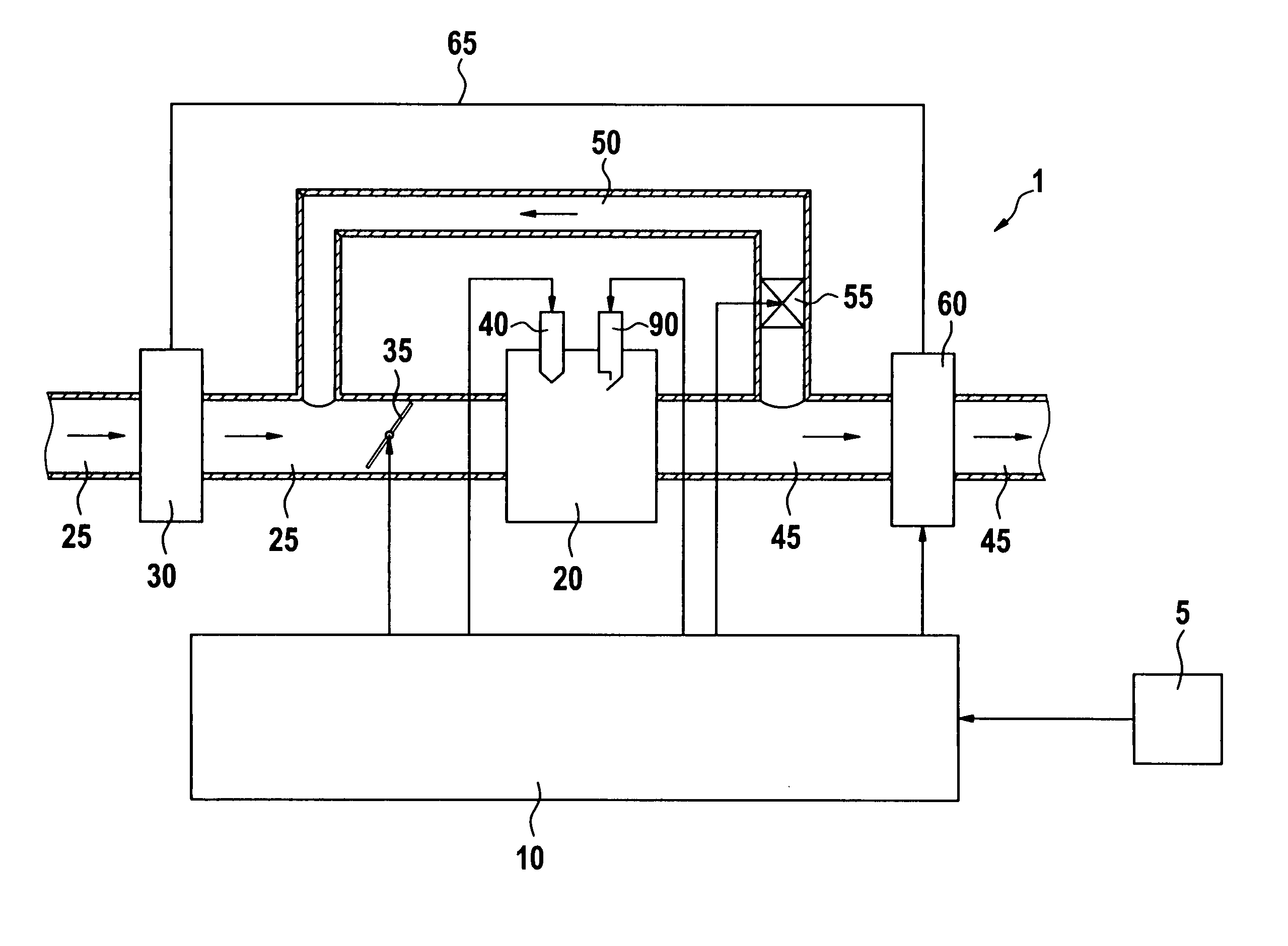
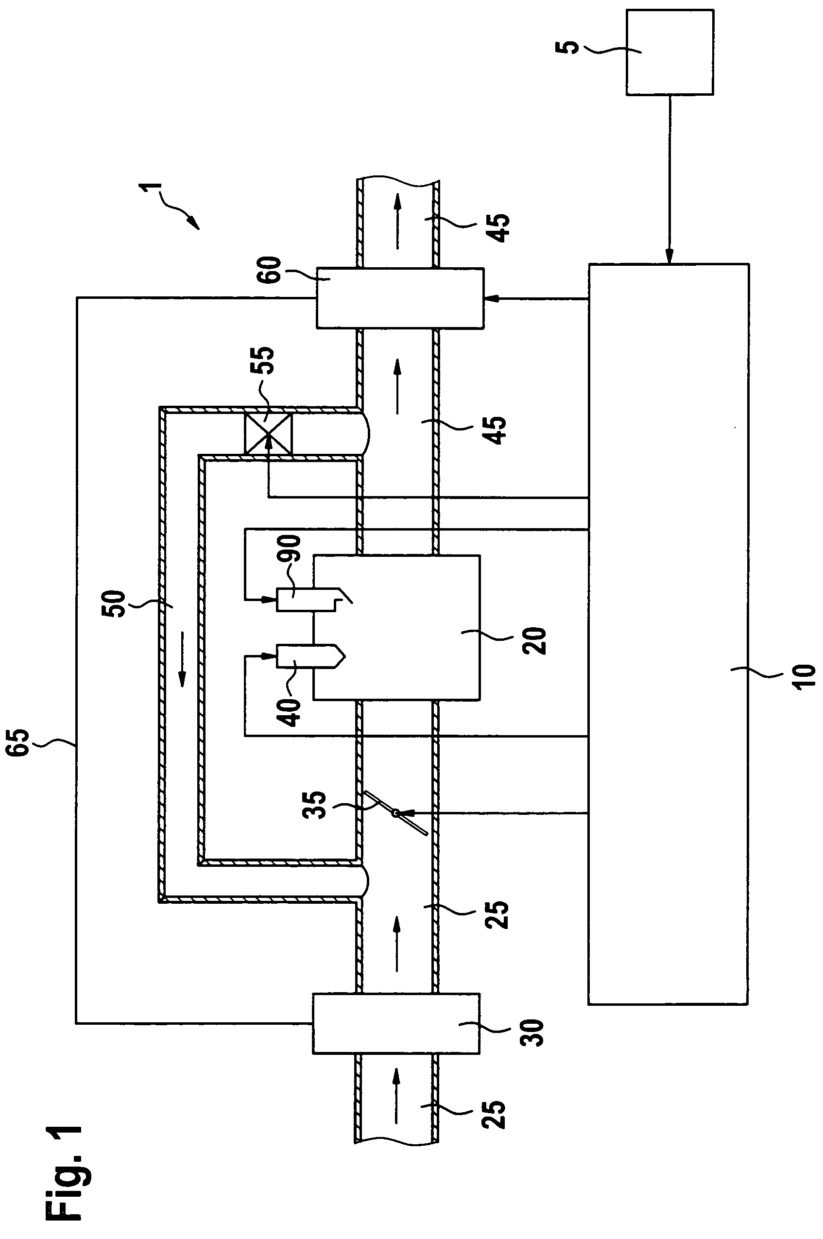
[0013]In FIG. 1, reference numeral 1 designates an engine of a vehicle. Engine 1 includes an internal combustion engine 20. Internal combustion engine 20 may take the form of, e.g. a spark-ignition engine or a diesel engine. In the following, it is assumed, for example, that internal combustion engine 20 takes the form of a spark-ignition engine. Internal combustion engine 20 is supplied with fresh air via an air inlet 25. The flow direction of the fresh air in air inlet 25 is indicated by arrows. In this context, a compressor 30 of, e.g. an exhaust-gas turbocharger, which compresses the supplied fresh air, may be situated in air inlet 25, as shown in FIG. 1. In air inlet 25, a throttle valve 35 for setting the amount of air supplied to a combustion chamber of internal combustion engine 20 not shown in FIG. 1 is positioned downstream from compressor 30 in the flow direction of the fresh air. To that end, the position of throttle valve 35 is controlled by a control unit 10. Fuel is i...


PUM


Abstract

A method and a device for operating an engine of a vehicle, which allow a power demand of a steering device supported by the engine To be dynamically compensated for. In this context, a derivative-action signal for adjusting an output variable to be output by the engine is generated as a function of a steering action.

Description

FIELD OF THE INVENTION[0001]The present invention relates to a method and a device for operating an internal combustion engine of a vehicle.BACKGROUND INFORMATION[0002]Steering devices in the form of power-steering systems may be supported by the internal combustion engine of the vehicle, in that the internal combustion engine provides torque for operating a servomotor.[0003]In addition, models, which estimate each current torque requirement of mechanically driven, ancillary components such as an air conditioner or power-steering system, may be stored in the control system for internal combustion engines or gasoline engines. With the aid of the torque requirement of the ancillary components ascertained in this manner, the supply of additional fresh air in an air-controlled system or the supply of additional fuel in a fuel-amount-controlled system may be appropriately adjusted, in order to cover the torque requirement of the ancillary components, without reducing a vehicle drive (pro...

Claims


Application Information

Patent Timeline
IPC IPC(8): F01L1/34F02D29/02B62D5/06B62D5/065F02D29/04F02D41/00F02D41/04F02D41/08
CPCB62D5/063B62D5/065F02D41/021F02D41/083F02D41/0002F02D2250/22
Inventor MAYER, RAINER
Owner ROBERT BOSCH GMBH
Why Eureka
Try Eureka