
Ultrasound sensor system

a technology of ultrasonic and sensor system, which is applied in the direction of mechanical vibration separation, instruments, specific gravity measurement, etc., can solve the problems of inability to achieve the direct direction of sound radiation in the direction of the weld spot, disadvantageous attachment of probes to the side of the electrode adapter, and more or less restricted freedom of movement of these robot arms, etc., to achieve the effect of improving the transmission/receiving power of the system, reducing the physical size and facilitating the s a sensor system and ultrasonic sensor system and ultrasonic radiation directed in the field of ultras ultrasonic radiation and sensor system and ultrasonic radiation and sensor system, which is applied in the field of ultrasonic field of ultrasonic field of ultrasonic field of ultrasonic field, which is applied in the direction of ultrasonic radiation directed in the direction of ultrasonic radiation, a technology, which is applied in the direction of ultrasonic direction of ultrasonic direction

Inactive Publication Date: 2007-04-10
ROBERT BOSCH GMBH
View PDF7 Cites 3 Cited by
  • Summary
  • Abstract
  • Description
  • Claims
  • Application Information

AI Technical Summary

Benefits of technology

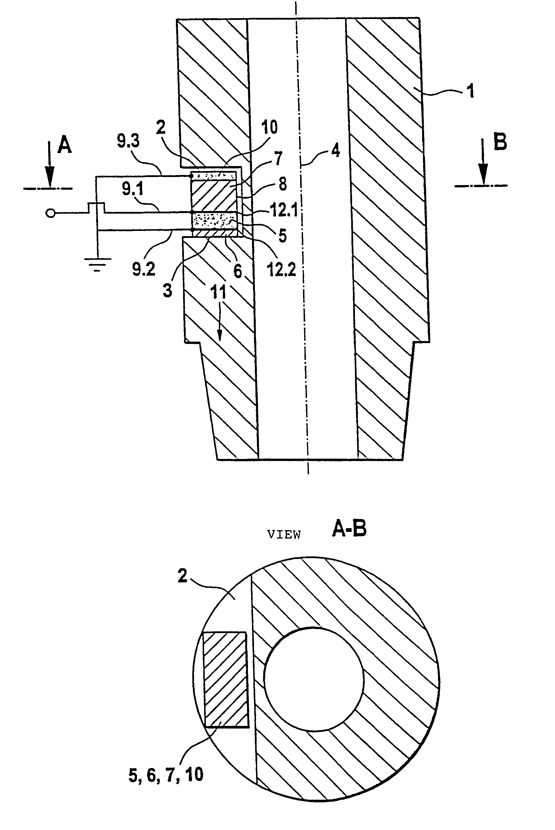
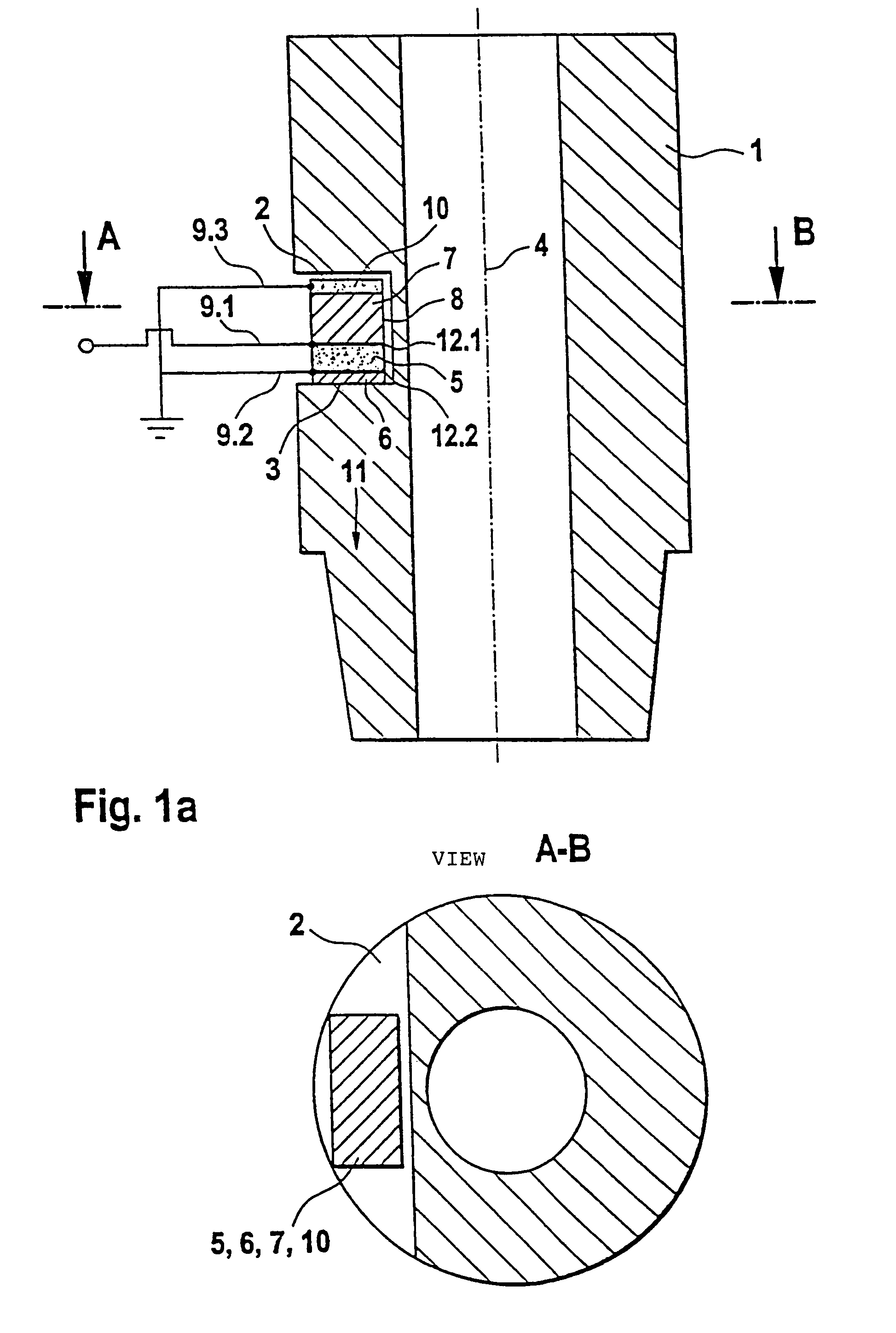
[0008]The object of the invention is attained by integrating the ultrasound sensor in a sensor carrier, whereby at least one material recess such as a groove is provided to accommodate ultrasound sensors. The ultrasound sensor can be accommodated in protected fashion, making this system suited for industrial use, e.g., using welding robots. Physical size can be reduced by using an arrangement of ultrasound sensors integrated in the sensor carrier, as opposed to arranging them on the side. Additionally, the ultrasound sensors can be more easily attached to the sensor carrier.
[0009]These material recesses form flat surfaces preferably in the direction of radiation or detection, which surfaces are positioned either perpendicular to the longitudinal axis of the sensor carrier so the main radiation direction of the ultrasound sensors is parallel to the longitudinal axis of the sensor carrier, or they are tilted toward the longitudinal axis of the sensor carrier in order to create other advantageous sound propagation directions.
[0010]In an advantageous further development, the ultrasound sensor comprises, in addition to a piezoelectric ply, at least one sound-damping and / or reverberating ply. This allows sound propagation to be directed in a desired direction, which improves the transmission / receiving power of this system.
[0011]A further advantageous embodiment provides an intermediate ply composed of non-piezoelectric material, the acoustic impedance of which nearly corresponds to the material of the sensor carrier or a value that is between sensor material and sensor carrier. This intermediate ply is preferably located between the sensor carrier and the piezoelectric ply generating the ultrasonic waves. This makes it possible to achieve good sound transmission between the piezoelectric element and the sensor carrier. Additionally, this intermediate ply ensures electrical insulation between piezoelectric element and sensor carrier.
[0012]In an advantageous further development, means are provided to prevent propagation of ultrasonic waves in a direction that extends radially to the longitudinal axis of the sensor carrier. For example, an intermediate space or a separating ply extends between the ultrasound sensor and the sensor carrier parallel to its longitudinal axis in order to prevent radial propagation of ultrasonic waves. Transmitter power and / or sensitivity of reception can thereby be improved.
[0013]An advantageous embodiment provides means for the electrical shielding of the piezoelectric ply in order to reduce perturbing actions.

Problems solved by technology

The disadvantages that result from radiation in the direction of the inner wall of the electrode instead of in the direction of the welding spot also apply without limitation for transverse waves.
Sound radiation directed entirely in the direction of the weld spot cannot be achieved with this, however.
Moreover, attaching probes to the side of the electrode adapter is disadvantageous in practice for further reasons.
The depth propagation of the probes plus that of the wedge-shaped attachments used leads to a situation in which, in automated production facilities where the welding electrodes are guided by robot arms, the freedom of motion of these robot arms is more or less restricted.
When subjected to such alternating stresses, glued joints run the risk of fatigue failures.
If a collision with an obstacle occurs, there is also a risk that a probe will be torn off immediately or even destroyed.
Such a system is therefore not sufficiently failsafe for long-term industrial use without further mechanical safety devices.
When different materials are used for attachment and electrode adapter, the different acoustic impedances lead to further reverberation losses.
The disadvantages caused by adhesive plies and sound refraction could only be prevented, then, if electrode adapter and attachment would be produced connected out of one material.
The production of a part shaped in such complicated fashion would be very costly, however.

Method used


Image

  • Ultrasound sensor system
  • Ultrasound sensor system
  • Ultrasound sensor system

Examples


Embodiment Construction

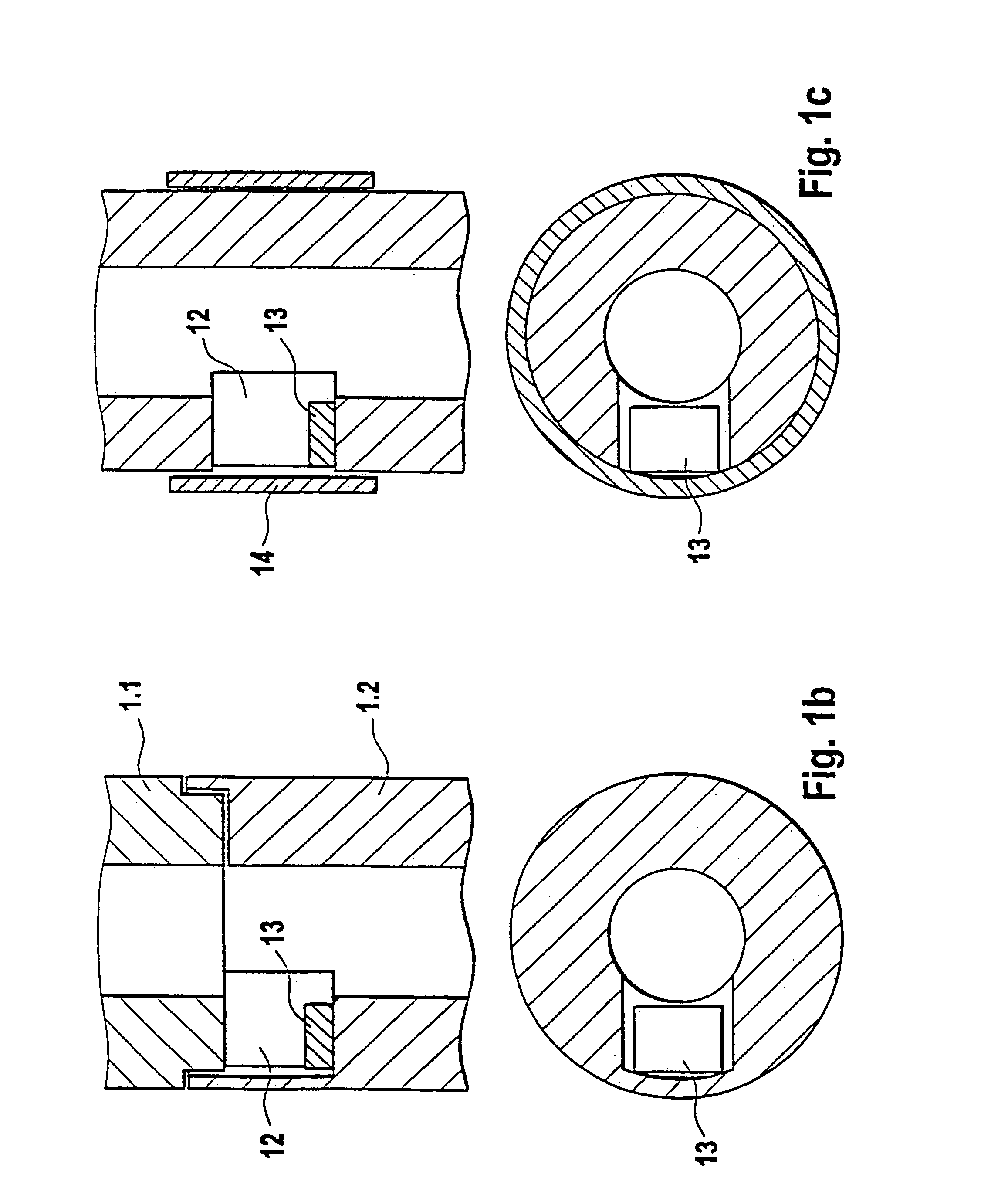
[0024]The exemplary embodiments are based on a potential application in welding electrodes. The electrode adapter forms the sensor carrier for at least one ultrasound sensor.

[0025]FIG. 1a shows the principle mode of operation of the ultrasound sensor system according to the invention using one of the potential exemplary embodiments as an example. For the fundamental mode of operation of the invention, it is irrelevant whether the welding electrodes are bipartite and comprise electrode adapter and cap, or how they are shaped on their back end, in order to be accommodated by a holder. These details will be left unpresented initially in this and the subsequent drawings. A recess 2 designed in the shape of a groove is created in the electrode adapter 1. The side of the groove facing the electrode tip forms a surface 3 that is perpendicular to the longitudinal axis 4 of the electrode adapter 1. A, e.g., rectangular, ply 5 composed of piezoelectric material is located on it. This is outfi...


PUM

PropertyMeasurementUnit
frequencyaaaaaaaaaa
self-weightaaaaaaaaaa

Abstract

The invention relates to an ultrasound sensor system, especially for a welding electrode, comprising a sensor (5, 6, 7, 10) which, during the detection process, passes ultrasonic waves of a desired oscillation mode into areas to be detected and / or detects ultrasonic waves. At least one material recess (2) is provided in a sensor support (1), and at least one sensor (5, 6, 7, 10) is arranged in said recess.

Description

RELATED ART[0001]The invention is based on an ultrasound sensor system according to the definition of the species in the independent claim.[0002]The evaluation procedure described in EP 653 061 B1 basically comprises the transmission of transverse waves instead of longitudinal waves through the intended welding region during the welding procedure. The amplitude of the through-transmission signal is captured on-line and used as controlled variable for amplitude and variation in time of the welding current. The transverse wave is selected because the influence of fluid formation in the weld nugget on the damping of a through-transmitted wave is very great with this wave mode. The amplitude—which changes markedly and in characteristic fashion over the course of the welding process—or the course of the transverse wave over time provides a reliable conclusion about the formation and size of the weld nugget and can therefore be used as manipulated variable for a control process.[0003]The ...

Claims


Application Information

Patent Timeline
Patent Type & Authority Patents(United States)
IPC IPC(8): G01N29/04B23K11/25G01N29/22G01N29/24
CPCG01N29/22G01N29/223G01N29/2487G01N2291/0421G01N2291/0422G01N2291/2636G01N2291/2672
Inventor STUMM, WOLFGANGARNDT, VOLKERBLUMENTRITT, NORBERTLACH, MICHAELPLATTE, MICHAEL
Owner ROBERT BOSCH GMBH
Learn More