System and method for breaking reentry circuits by cooling cardiac tissue

a technology of reentry circuit and cooling circuit, which is applied in the field of system and method, can solve the problems of destroying the circuit, tachycardia or abnormally slow (bradycardia) heartbeats, cell irreversible changes, etc., and achieves superior cardiac contraction, faster impulse conduction, and enhanced cardiac contractility.

Inactive Publication Date: 2007-04-10
MR3 MEDICAL LLC
View PDF166 Cites 92 Cited by
  • Summary
  • Abstract
  • Description
  • Claims
  • Application Information

AI Technical Summary

Benefits of technology

[0024]It is a further aspect of the present invention to inhibit the conduction of certain spurious electrical impulses in the heart by cooling cardiac tissue affected by re-entry circuits.
[0034]In one aspect of the invention, both cooling and biphasic electrical stimulation is administered to the cardiac muscle. The anodal stimulation component of biphasic electrical stimulation augments cardiac contractility by hyperpolarizing the tissue prior to excitation, leading to faster impulse conduction, more intracellular calcium release, and the resulting superior cardiac contraction. The cathodal stimulation component eliminates the drawbacks of anodal stimulation alone, resulting in effective cardiac stimulation at a lower voltage level than would be required with anodal stimulation alone. This in turn, extends pacemaker battery life and reduces tissue damage.
[0035]In a second aspect of the invention, cooling is applied to the cardiac tissue and biphasic electrical stimulation is administered to the cardiac blood pool, that is, the blood entering and surrounding the heart. This enables cardiac stimulation without the necessity of placing electrical leads in intimate contact with cardiac tissue, thereby diminishing the likelihood of damage to this tissue. The stimulation threshold of biphasic stimulation administered via the blood pool is in the same range as standard stimuli delivered directly to the heart muscle. Through the use of biphasic electrical stimulation to the cardiac blood pool it is therefore possible to achieve enhanced cardiac contraction, without skeletal muscle contraction, cardiac muscle damage or adverse effects to the blood pool.
[0047]In another embodiment of the present invention, methods for suppressing arrhythmia in a patient are provided. A heat-transfer operator is implanted at each of one or more targeted portions of a patient's heart. At least one heat-transfer operator is operated to cool at least one targeted portion of the heart, thereby suppressing the arrhythmia.

Problems solved by technology

In the absence of circulation, cells begin to undergo irreversible changes that lead to death.
When the electrical “circuits” of the heart do not operate optimally, an arrhythmia may result.
An arrhythmia may result in unusually fast (tachycardia) or unusually slow (bradycardia) heartbeats.
Eliminating the slow conductance elements of a reentry circuit destroys the circuit.
Both atrial fibrillation and atrial flutter increase the risk of stroke.
The risk of developing atrial fibrillation increases dramatically with age.
WPW syndrome may result in extremely rapid heartbeats and could potentially result in death.
Unlike AF, it is life threatening because it results in 350 beats per minute or higher.
The heart cannot keep that rate up for more than a few minutes without treatment (e.g., with a defibrillator).
Any interference or block in cardiac impulse conduction may cause an arrhythmia or marked change in the rate or rhythm of the heart.
However, until the work embodied in U.S. Pat. Nos. 5,871,506 and 6,141,586 for example, anodal current was thought not to be useful clinically.
However, due to trauma associated with the stimulation, scar tissue grows at the interface between the implanted cardiac pacer leads and the myocardium.
A drawback to such an approach is that the higher stimulation level causes more trauma to the cardiac tissue than would a lower level of stimulation, and hence promotes the formation of scar tissue, thereby boosting the capture threshold.
The higher stimulation level also shortens battery life.
This is not desirable, as a shorter battery life necessitates more frequent surgery to implant fresh batteries.
Another drawback is the potential for patient discomfort associated with this higher stimulation level.
Lastly, the higher stimulation is less effective, due to entry block.
However, this technique did not result in reversion to a sinus rhythm for all victims of cardiac conduction disorder.

Method used


Image

  • System and method for breaking reentry circuits by cooling cardiac tissue
  • System and method for breaking reentry circuits by cooling cardiac tissue
  • System and method for breaking reentry circuits by cooling cardiac tissue

Examples


Embodiment Construction

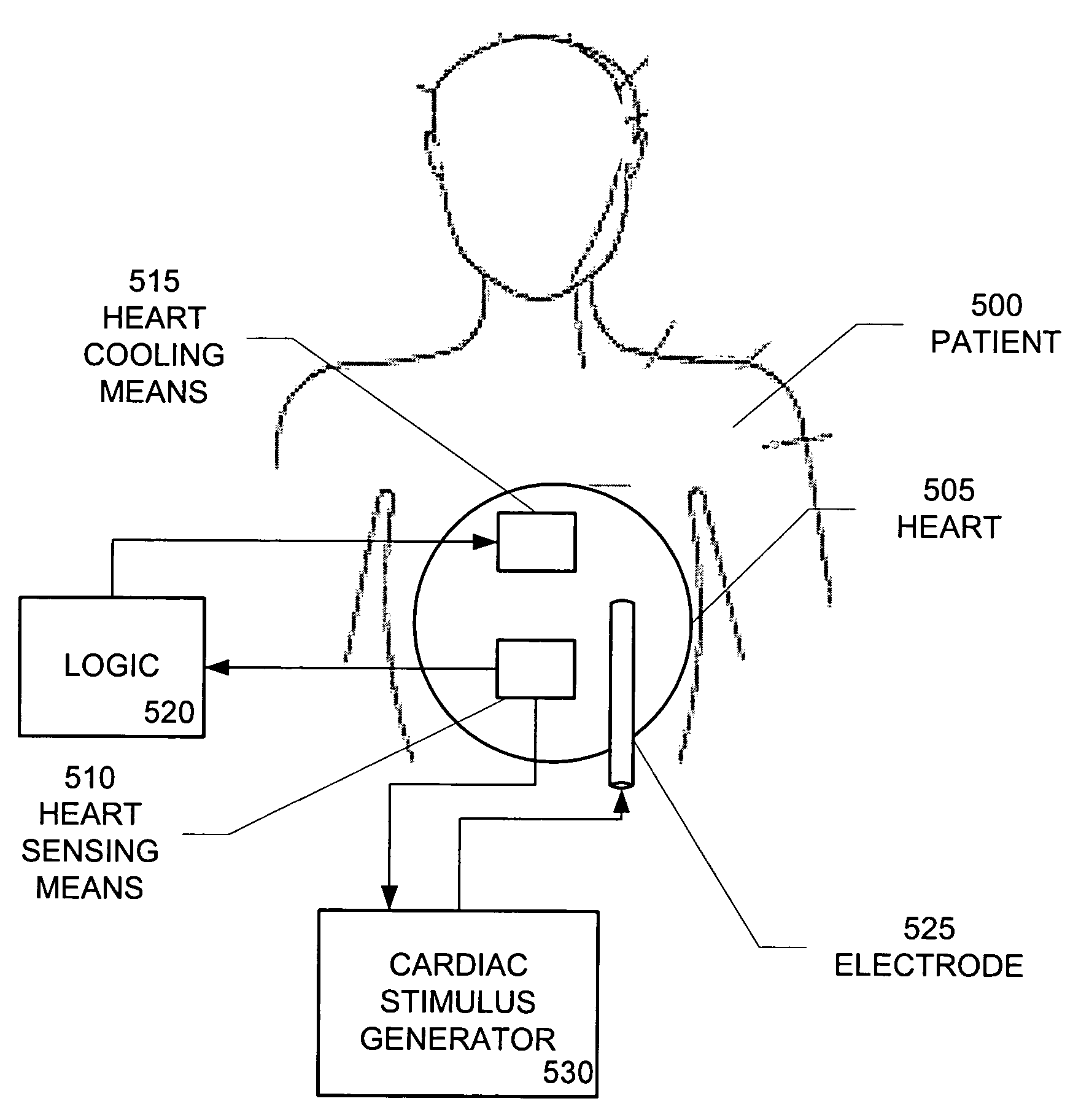
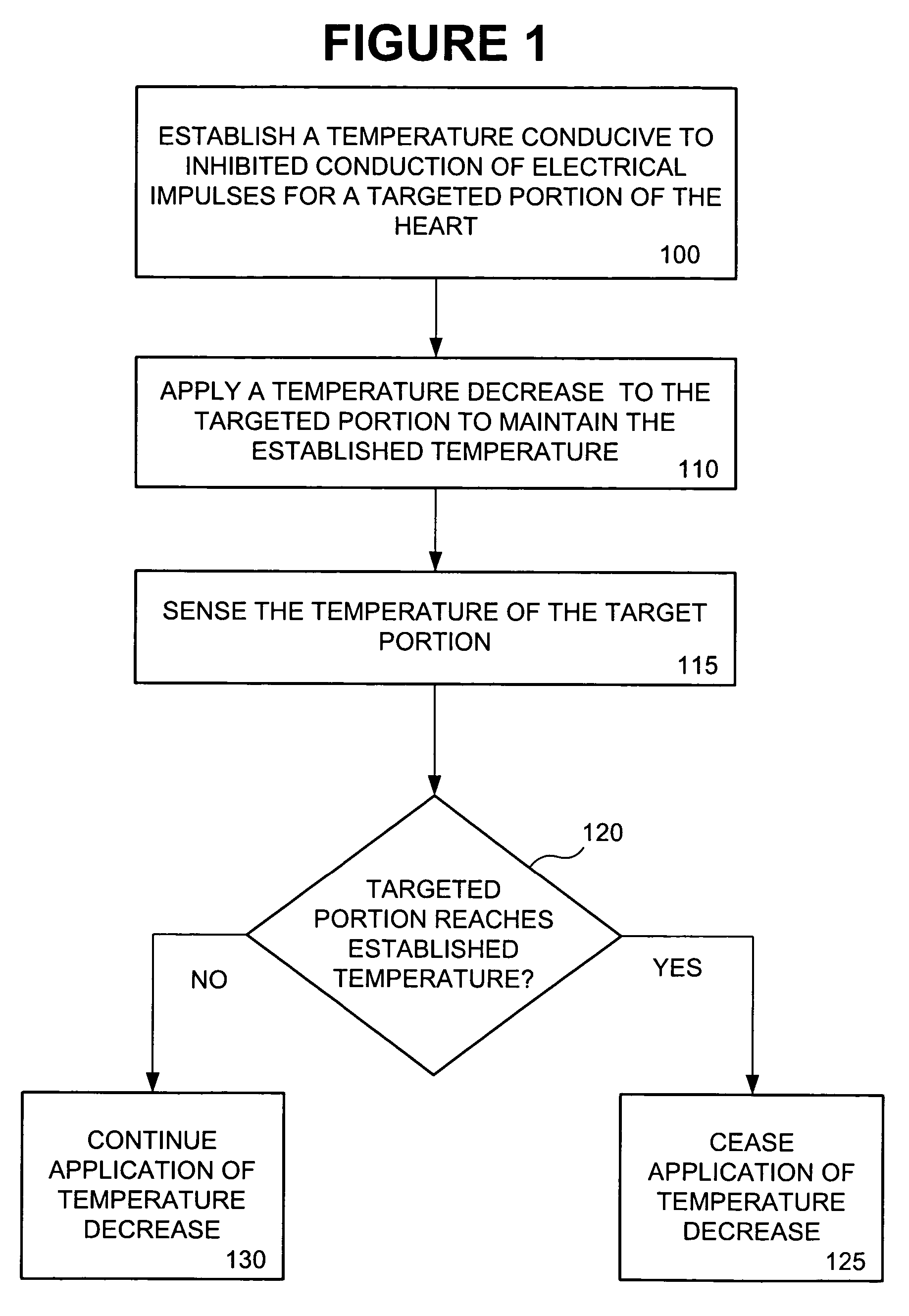
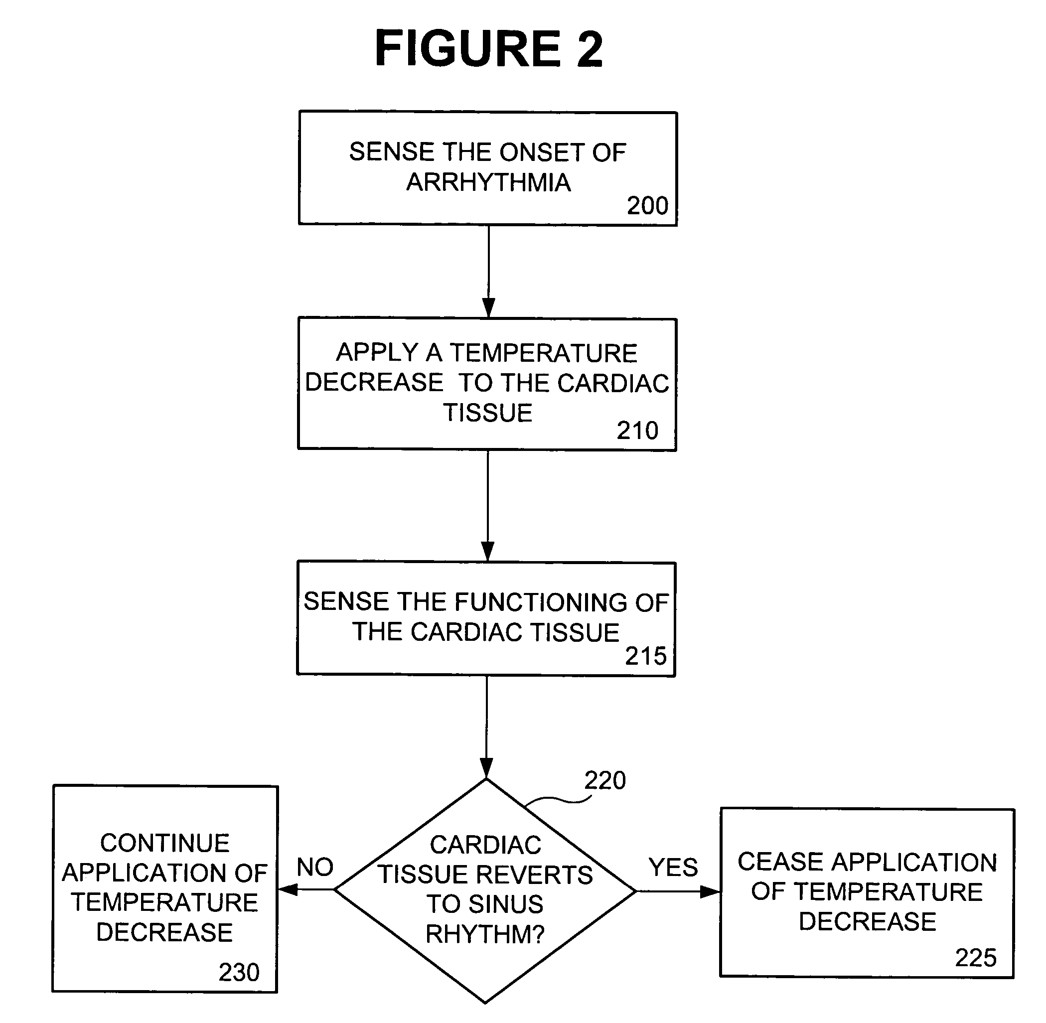
[0056]Embodiments of the present invention provide systems and methods for treating cardiac tissue by cooling the cardiac tissue to inhibit the conduction of certain electrical signals in cardiac tissue and decrease the duration of tachycardia and enhance the effects of pacing and defibrillation stimuli. In the description of these embodiments, reference is made to sensing a “symptom” indicative of a condition of the heart that may be treated by application of the present invention. For the purpose of the present invention, the term “symptom” is used broadly to encompass any sign or indication of such a condition that can be detected through direct or indirect sensing of physiological parameters.

[0057]An embodiment of the present invention comprises an implantable cardiac treatment / stimulation device designed to inhibit the conduction of spurious electrical signals in cardiac tissue without pacing. The technique applied in the implantable device comprises a cooling element for cooli...


PUM


Abstract

Systems and methods to inhibit the conduction of certain spurious electrical impulses in the heart. Inhibition of spurious electrical impulses in the heart is accomplished by cooling one or more targeted portions of the heart. Optionally, inhibition of spurious electrical impulses may be accomplished by cooling of cardiac tissue in combination with pacing of the heart.

Description

CROSS REFERENCE TO RELATED APPLICATIONS[0001]This application is a continuation-in-part of U.S. patent application Ser. No. 09 / 929,478 filed Aug. 14, 2001, now U.S. Pat. No. 6,895,274, which is a continuation of U.S. Ser. No. 09 / 231,570 application filed Jan. 14, 1999, now U.S. Pat. No. 6,295,470, which is a continuation-in-part of U.S. patent application Ser. No. 08 / 699,552, filed Aug. 19, 1996, now U.S. Pat. No. 5,871,506 and a continuation-in-part of U.S. patent application Ser. No. 10 / 053,750 filed Jan. 21, 2002, pending, which is a continuation of U.S. patent application Ser. No. 09 / 690,947, filed Oct. 18, 2000, now U.S. Pat. No. 6,341,235, which is a continuation-in-part of U.S. patent application Ser. No. 09 / 008,636 filed Jan. 16, 1998, now U.S. Pat. No. 6,136,019, which is a continuation-in-part of U.S. patent application Ser. No. 08 / 699,552, filed Aug. 19, 1996, now U.S. Pat. No. 5,871,506. This application claims priority under 35 U.S.C. § 119(e) from provisional applicati...

Claims


Application Information

Patent Timeline
Patent Type & Authority Patents(United States)
IPC IPC(8): A61N1/37A61BA61N1/28A61N1/362A61N1/365A61N1/39
CPCA61F7/12A61N1/3622A61B2017/00044A61F2007/0056A61F2007/0075A61F2007/0095A61F2007/126A61N1/3624
Inventor MOWER, MORTON M.
Owner MR3 MEDICAL LLC
Why Eureka
Try Eureka