Engine suction air flow rate measuring device

a technology of flow rate and measuring device, which is applied in the direction of volume/mass flow by differential pressure, instruments, analogue processes for specific applications, etc., can solve the problems of reducing the accuracy of measuring accuracy, and limiting the design of intake pipes. achieve the effect of reducing the flow resistance and deteriorating the measurement accuracy

Inactive Publication Date: 2007-04-17
MATSUO NORITAKA
View PDF7 Cites 3 Cited by
  • Summary
  • Abstract
  • Description
  • Claims
  • Application Information

AI Technical Summary

Benefits of technology

[0013]Accordingly, it is a primary object of the present invention to provide an engine intake air flow meter for measuring an amount of intake air for each cylinder without increasing of flow resistance and deterioration in measuring accura

Problems solved by technology

A hot-wire flow meter has the advantage of the ability of measuring a mass flow rate of pulsation flow with high response, while the disadvantages of requiring some additional devices for detecting a flow direction when adopted for measurement in a flow field where both of the order and reverse direction flows occur alternately, and causing a measurement error by stains on a hot-wire surface. FIG. 17 shows an example of a multi-cylinder engine with a multi-point injection system employing a hot-wire flow meter.
However, there are the problems such that an output variable of the flow meter is related to a volumetric flow rate that must be converted to a mass flow rate for air-fuel ratio control application, hence a temperature sensor and a pressure sensor must be employed in combination with a flow sensor, some devices for detecting a flow direction is needed as well as a hot-wire flow meter, and further a design of an intake pipe is restricted because a calibration characteristics of an output of a sensor against a flow rate strongly depend on the designs of a cone to generate Karman vortices and a passage around the cone.
Therefore, it is difficult to measure an amou

Method used


Image

  • Engine suction air flow rate measuring device
  • Engine suction air flow rate measuring device
  • Engine suction air flow rate measuring device

Examples


first embodiment

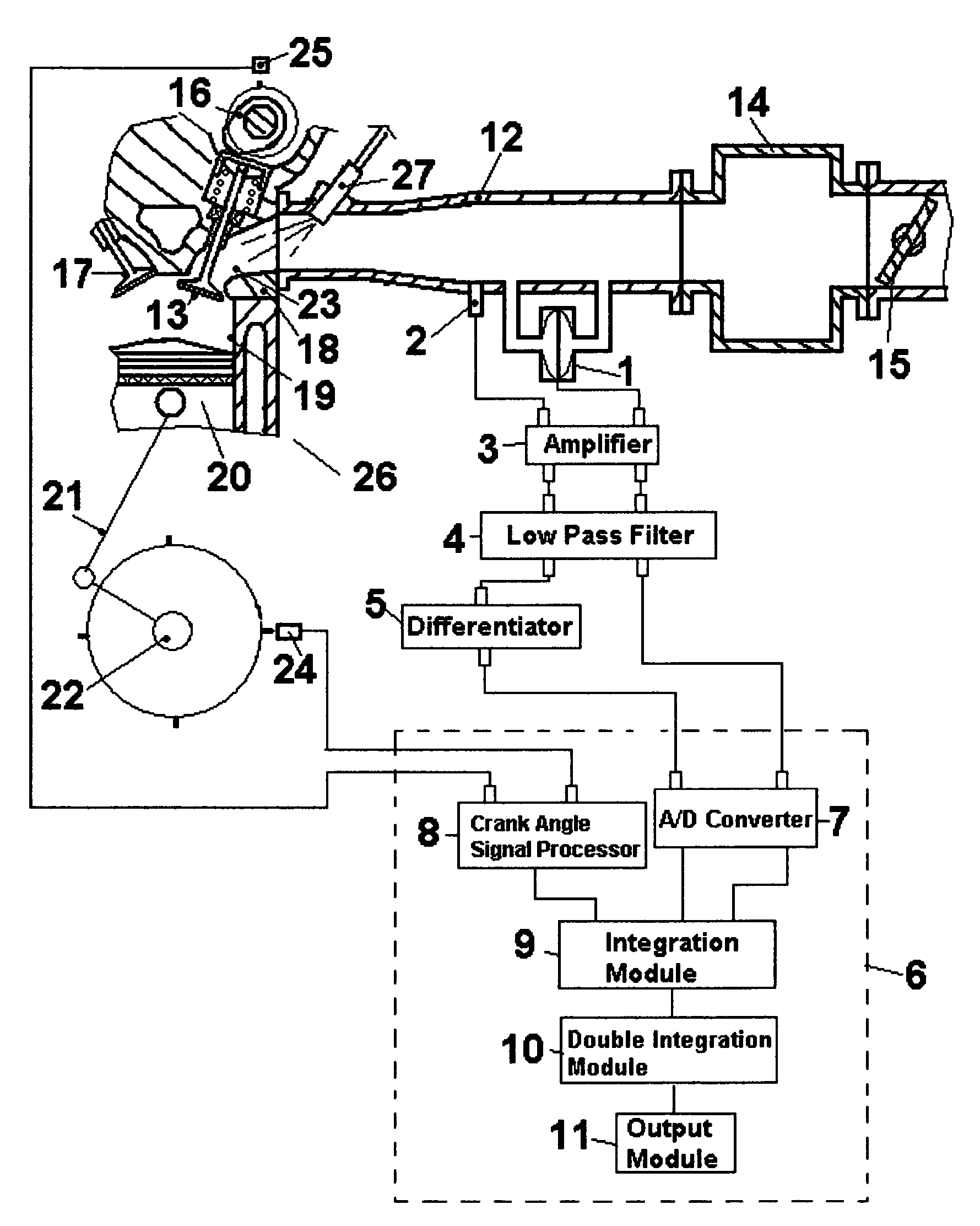
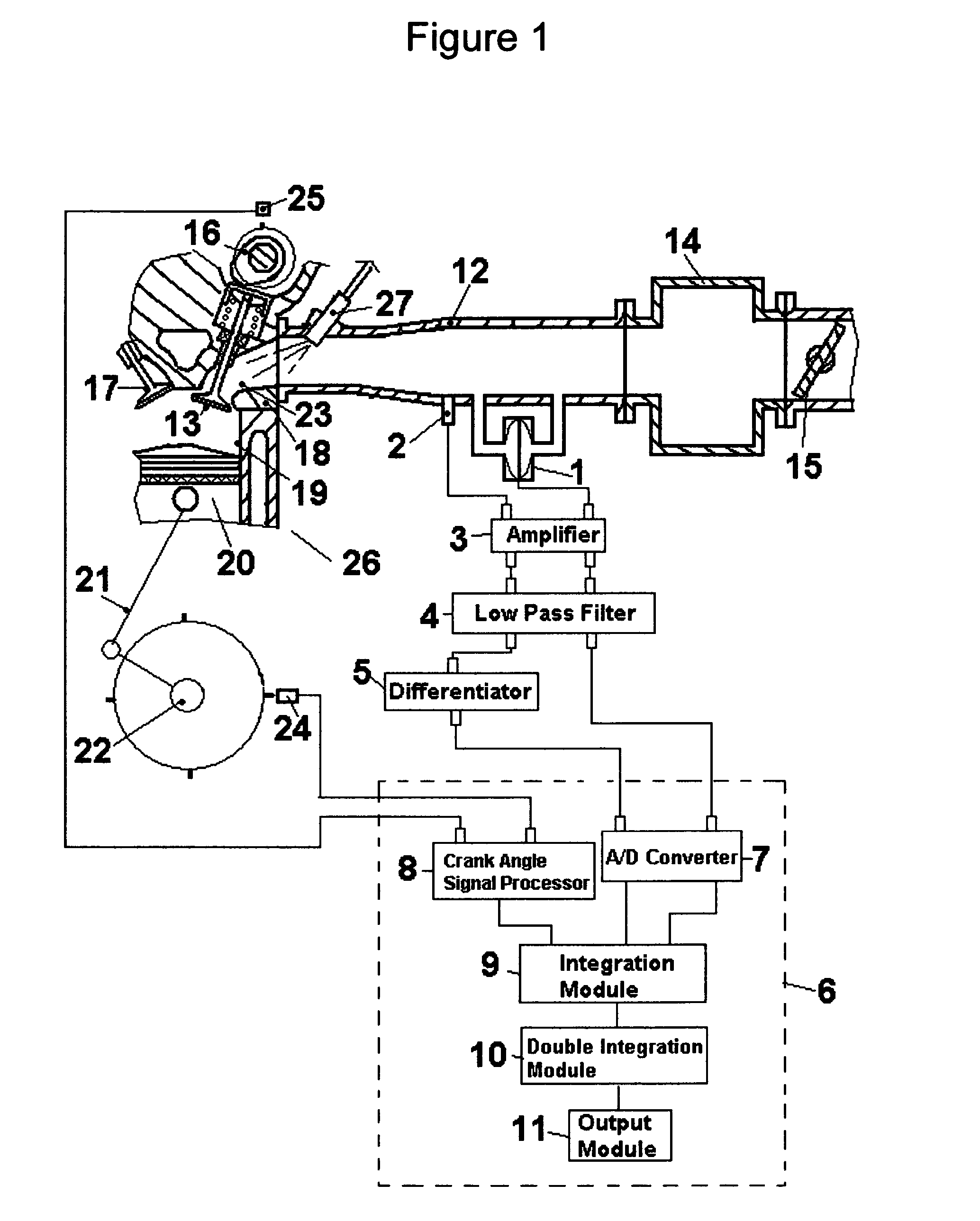
[0064]FIG. 1 illustrates particularly a construction of a cylinder of a multi-cylinder engine corresponding to a sectional view taken along the plane A–A′ of FIG. 2, which essentially comprise essences of the present invention that is basically common for every cylinder of said multi-cylinder engine. In FIG. 1, a cylinder 19 is in communication with an intake system comprising an intake port 23, an intake pipe 12, an air collector 14, a throttle valve 15, and an air cleaner box not shown, and a communication between cylinder 19 and the intake system is intermittently interrupted by an intake valve 13 that is constrained to reciprocative motion by a cam 16. A fuel injector 27 injects an amount fuel determined from an air flow mass measured for each cylinder and a target air-fuel ratio. Intake pipe 12 has a section with a constant cross-sectional area where a differential pressure sensor 1 and a pressure sensor 2 are installed. Preferably sensors with sufficiently high natural frequen...

third embodiment

[0080]FIG. 8 shows a schematic view of this invention. This embodiment features that three or more pressure sensors with equal sensitivity to pressures are employed for measuring a differential pressure to allow a choice of a combination of two of said pressure sensors based on engine running conditions. A typical choice of the combination of the sensors is such that two sensors in a longer distance spaced apart are used through a low engine speed range where an averaged frequency of intake flow pulsation is low and pressure gradient along the intake pipe is small, while two sensors in a shorter distance spaced apart are used through a high engine speed range. The figure illustrates an example employing three pressure sensors 2, 36, and 37. In this embodiment output signals from said three sensors are transmitted to a differential pressure processor 38 after being processed by amplifier 3 and low pass filter 4 as well as noted in paragraph [0030], and A / D converter 7 that converts a...

fourth embodiment

[0081]FIG. 9 shows a schematic view of this invention. This embodiment features that two points in an intake pipe for a differential pressure measuring are both set in either of the upstream side of throttle valve 15 or the downstream side. It is especially suited to an application for an engine employing independent throttles for each intake pipe for such as motorcycles, racing cars, or sports cars.

[0082]FIG. 10 shows a schematic view of a fifth embodiment of this invention. This embodiment features that two points for measuring a differential pressure are located in a section of an intake pipe where the cross-sectional area is varying lengthwise, and it is particularly alternative for the first embodiment for an application for such an engine employing an intake pipe with a form that it continuously expands toward to its open end as its resultant optimized design for increasing a volumetric efficiency by dynamic effects of intake flow, such as inertia effect or pulsation effect. I...


PUM


Abstract

The present invention embodies an engine intake air flow meter measuring a mass flow rate based on measured pressures in an intake pipe, such as a pressure difference between two points and a pressure at a point. Calculations for integration and double integration of the pressure difference are performed, and both values of integration and double integration are corrected at a moment when an air flow rate is detected to be a zero based on a value of a time derivative of the pressure. Then a mass flow rate and an amount of air are calculated by the value of integration and the value of double integration respectively.

Description

BACKGROUND OF THE INVENTION[0001]Today, most of automobile engines employ a fuel injection system to control an air-fuel ratio accurately for improving exhaust emissions or fuel consumption. In a fuel injection engine, an amount of fuel to be injected is determined by an amount of mass of intake air and a desired air-fuel ratio. In particular, with a multi-cylinder engine, an air flow meter is required to have the ability of measuring an amount of intake air for each cylinder with high accuracy and response. Air flow meters in common use for a fuel injection engine today or in the past are such as a vane type flow meter, a hot-wire flow meter, or a Karman vortices flow meter.[0002]A vane type flow meter is not being used today for production engines because of the disadvantages such that a vane causes a large amount of flow resistance, and an inertia of vane lowers response under transient states of engine running, though, from the viewpoint of principle, it has the advantage of cap...

Claims


Application Information

Patent Timeline
IPC IPC(8): G01M15/00G01F1/34
CPCG01F1/34
Inventor MATSUO, NORITAKA
Owner MATSUO NORITAKA
Why Eureka
Try Eureka