Torsionally flexible coupling, a mold, and a method of producing same

a torsional flexible and coupling technology, applied in the direction of slip coupling, gearing, hoisting equipment, etc., can solve the problems of unpleasant noise and unwanted rattling sounds, and achieve the effect of reducing the noise of the operation

Inactive Publication Date: 2007-04-17
VIBRACOUSTIC
View PDF24 Cites 29 Cited by
  • Summary
  • Abstract
  • Description
  • Claims
  • Application Information

AI Technical Summary

Benefits of technology

[0005]An object of the present invention is to improve upon a torsionally flexible coupling, so that operating noises are effectively reduced.

Problems solved by technology

Due to the sliding-contact bearing, which has been installed with some play, unwanted rattling sounds occur during the intended use of the torsionally flexible coupling, and these are especially unpleasant when the torsionally flexible coupling is used in quiet, high-class motor vehicles, for example.

Method used


Image

  • Torsionally flexible coupling, a mold, and a method of producing same
  • Torsionally flexible coupling, a mold, and a method of producing same
  • Torsionally flexible coupling, a mold, and a method of producing same

Examples


Embodiment Construction

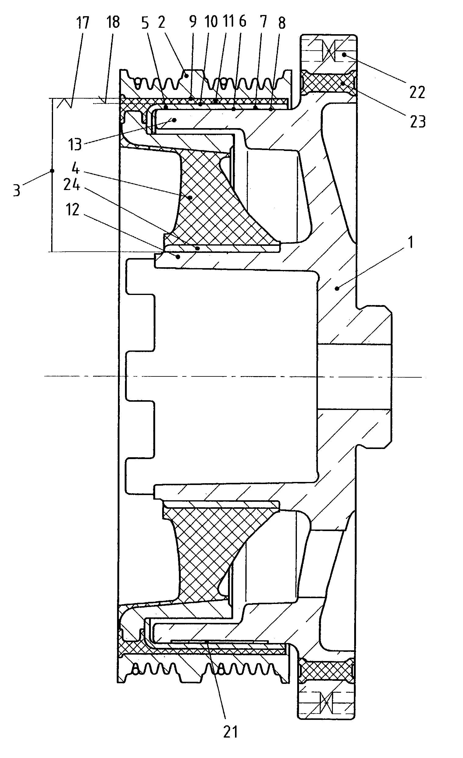
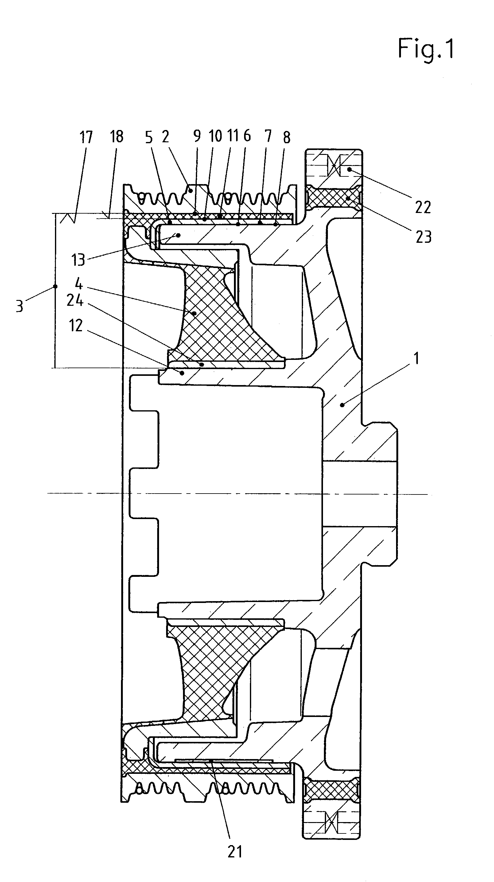
[0030]FIG. 1 shows the sectional view of an exemplary embodiment of a torsionally flexible coupling. The coupling includes a hub ring 1, which is attached in a rotationally fixed manner to a crankshaft (not shown here) of an internal combustion engine. Hub ring 1 is made of a metallic material and is surrounded by pulley 2 at a radial distance. A spring body 4, which is made of a rubber-elastic material, connects hub ring 1 to pulley 2 in a torsionally flexible manner but allows comparatively great rotation of hub ring 1 in the circumferential direction of the coupling, relative to pulley 2. Spring body 4 is situated in gap 3 formed by this distance.

[0031]In addition, a sliding-contact bearing 5 is situated in gap 3 formed by this distance. Sliding-contact bearing 5 is necessary because comparatively soft spring body 4 is unable to adequately guide hub ring 1 and pulley 2 relative to one another. Due to the use of sliding-contact bearing 5, hub ring 1 and pulley 2 are excellently mo...


PUM


Abstract

A torsionally flexible coupling has a hub ring and a vibrationally isolated pulley surrounding the hub ring at a radial distance, a spring body made of a rubber-elastic material being situated in the gap formed by the distance, and comprises a sliding-contact bearing for mutual support of the hub ring and the pulley, the sliding-contact bearing having a sliding-contact surface on the side facing the hub ring or the pulley, the sliding-contact surface having at least one elastically flexible projection in the radial direction which comes in contact with the surface of the hub ring or the pulley under elastic prestress.

Description

[0001]Priority to German Patent Application No. 102 11 640.7-12, filed Mar. 15, 2002 and hereby incorporated by reference herein, is claimed.BACKGROUND INFORMATION[0002]The present invention relates to a torsionally flexible coupling.[0003]Such couplings are known in general and include a hub ring and a vibrationally isolated pulley surrounding the hub ring at a radial distance, a spring body made of a rubber-elastic material being situated in the gap formed by the distance, and a sliding-contact bearing for mutual support of the hub ring and the pulley. The sliding-contact bearings used are usually constructed of metallic materials in multiple layers. A sliding-contact surface of the bearing may be formed by a thin layer of a copper alloy and therefore has adequately good dry-running properties when insufficiently lubricated.[0004]Due to their function, conventional sliding-contact bearings must be mounted with a small radial play in the gap, which is delimited by the concentric ma...

Claims


Application Information

Patent Timeline
Patent Type & Authority Patents(United States)
IPC IPC(8): F16D3/00F16D3/68F16D3/76F16D7/02F16F15/12F16H55/36
CPCF16D3/68F16D3/76F16H55/36Y10T74/2131F16H2055/366
Inventor HUBER, WINFRIED
Owner VIBRACOUSTIC
Why Eureka
Try Eureka