
Control device for vehicular opening/closing body

a control device and vehicular technology, applied in the direction of motor/generator/converter stopper, dynamo-electric converter control, electric controller, etc., can solve the problems of increasing the duty ratio of the drive motor, even though a value thereof is small, and the pinching load is inevitable, so as to reduce the pinching load and avoid the influence of load

Active Publication Date: 2007-04-17
NISSAN MOTOR CO LTD
View PDF11 Cites 11 Cited by
  • Summary
  • Abstract
  • Description
  • Claims
  • Application Information

AI Technical Summary

Benefits of technology

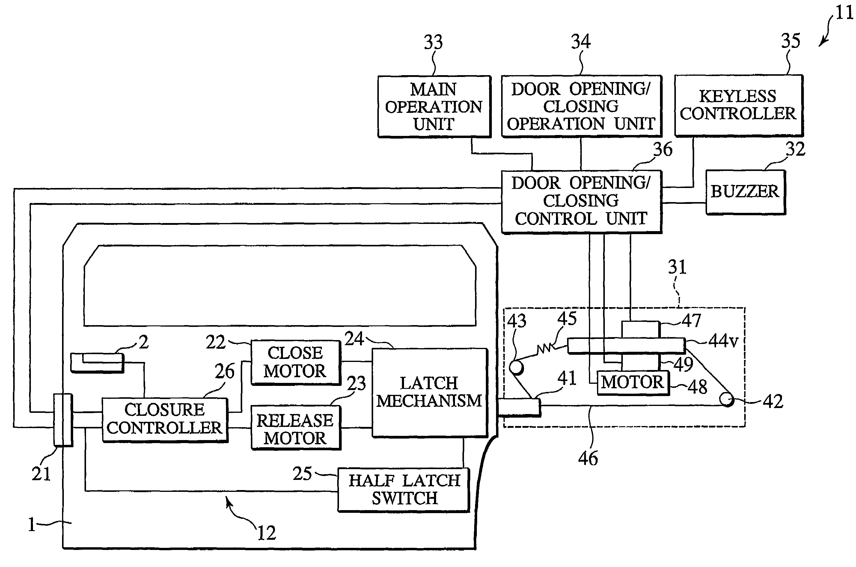
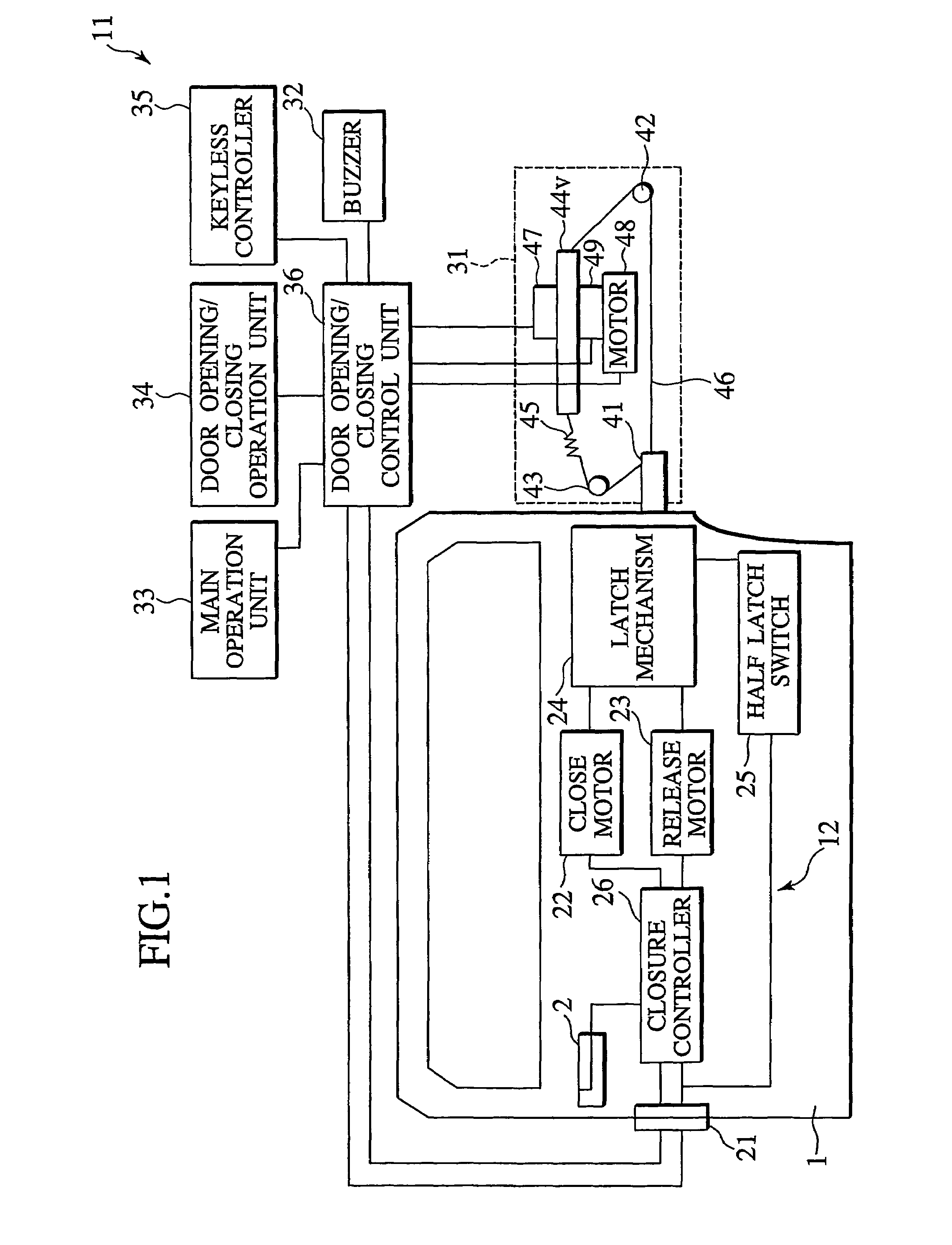
The present invention is a control device for a vehicular opening / closing body that reduces the pinching load even if the speed of the opening / closing body is lowered due to the occurrence of pinching. The control device includes an actual speed detecting unit, a target speed generating unit, a duty ratio calculating unit, and a gain setting unit. The duty ratio calculating unit calculates the duty ratio based on an addition result obtained by adding a first multiplication value in which the speed difference is multiplied by a proportional gain, a second multiplication value in which an integral value of the speed difference is multiplied by an integral gain, and a third multiplication value in which the actual opening / closing body speed is multiplied by a feedback gain. The technical effect of the invention is to reduce the pinching load by lowering the actual speed of the opening / closing body to an extent enough to avoid the influence of the load.

Problems solved by technology

However, in the above-described technology, in the case where the pinching occurs and the actual speed of the slide door is lowered, the duty ratio of the drive motor has been increased though a value thereof has been small.
Therefore, the torque of the drive motor has been increased though a value thereof has been small, leading to a problem of an inevitable increase of a pinching load.

Method used


Image

  • Control device for vehicular opening/closing body
  • Control device for vehicular opening/closing body
  • Control device for vehicular opening/closing body

Examples


first embodiment

[0058]FIG. 5 is a diagram showing a configuration of a control system including the duty ratio calculation unit 78 according to the present invention, the control system performing negative feedback control based on a speed difference between the target door speed VL and the actual door speed V. In FIG. 5, the duty ratio calculation unit 78 includes the first adder 81 receiving the target door speed and a negative value of the actual door speed, the proportional gain operational unit 82, the integration operational unit 83, the integral gain operational unit 84, and the second adder 85 adding the output of the proportional gain operational unit 82 and the output of the integral gain operational unit 84 to supply the duty cycle signal indicating the duty ratio. In the duty ratio calculation unit 78, the proportional gain of the proportional gain operational unit 82 and the integral gain of the integral gain operational unit 84 are set by the feedback gain setting unit 79. In FIG. 5, ...

second embodiment

[0069]FIG. 8 is a diagram showing a configuration of a control system, which includes the duty ratio calculation unit 78 according to the present invention, and is similar to that of FIG. 5. In FIG. 8, this duty ratio calculation unit 78 includes the first adder 81 receiving the target door speed and a negative value of the actual door speed, the proportional gain operational unit 87, the integration operational unit 83, the integral gain operational unit 84, the second adder 85, and the feedback gain operational unit 88. In this duty ratio calculation unit 78, the proportional gain of the proportional gain operational unit 82, the integral gain of the integral gain operational unit 84, and the feedback gain of the feedback gain operational unit 88 are set by the feedback gain setting unit 79.

[0070]When the target door speed VL and the actual door speed V are provided to the duty ratio calculation unit 78, the actual door speed is subtracted from the target door speed by the first a...

third embodiment

[0079]Next, the processing procedure when the integral gain K1, the proportional gain K2, the feed forward gain K3 and the proportional gain K5 are set by the above-mentioned door opening / closing control unit 36 to generate the duty cycle signal in the third embodiment will be described with reference to FIGS. 11, 12 and 13.

[0080]First, the door opening / closing control unit 36 performs processing of the flowchart shown in FIG. 11 in the door position calculation unit 74, thus calculating the moving direction and the door position of the slide door 1. Subsequently, the door opening / closing control unit 36 performs processing of the flowchart shown in FIG. 12 or 13, thus generating the duty cycle signal.

[0081]Next, a method for calculating the door position by the door position calculation unit 74 will be described with reference to FIG. 11.

[0082]In FIG. 11, when the slide door 1 actually moves and a door drive pulse is provided from the pulse encoder 47, a count value (FreeRun) of an...


PUM


Abstract

A control device for a vehicular opening / closing body is provided with a duty ratio calculator (78), which calculates a duty ratio when power supplied to a door drive motor (48) allowing an opening / closing body to open / close is subjected to duty control based on a result of adding first second multiplication values, the first multiplication value being obtained by multiplying a speed difference between a target opening / closing body speed and an actual opening / closing body speed by a negative proportional gain, and the second multiplication value being obtained by multiplying an integral value of the speed difference by an integral gain.

Description

TECHNICAL FIELD[0001]The present invention relates to a control device for a vehicular opening / closing body, which is provided in a vehicle and controls a speed of the vehicular opening / closing body opening / closing, for example, when an occupant gets on / off the vehicle.BACKGROUND ART[0002]Heretofore, a power slide door system has been known, which opens / closes a slide-type door mechanism provided in a vehicle by a drive force of a motor. This type of control device for opening / closing a vehicle slide door, which automatically opens / closes the vehicle slide door by driving the motor, is provided with a revolution number detection unit for detecting a revolution number of the motor. A technology of calculating a moving speed of the slide door based on a revolution number of the motor per predetermined time, which is detected by the revolution number detection unit, and of controlling the drive force of the motor, for example, a duty ratio in a PWM (Pulse Width Modulation) control base...

Claims


Application Information

Patent Timeline
Patent Type & Authority Patents(United States)
IPC IPC(8): H02P1/00H02P1/22H02P1/40H02P3/00H02P3/20E05F15/00E05F15/14G05B19/19
CPCG05B19/19G05B2219/41021G05B2219/41026E05F15/646G05B2219/45242E05Y2900/531E05F15/40G05B2219/42115G05B13/02
Inventor KIDOKORO, HITOSHI
Owner NISSAN MOTOR CO LTD
Learn More