Backplane configuration with shortest-path-relative-shift routing

a backplane and relative shift technology, applied in the field of large electronic systems, can solve the problems of limiting reliability, imposing practical limits of a few billion bits per second on the maximum system throughput, and preventing the creation of a truly universal platform. the effect of reducing the trace length of the backplan

Inactive Publication Date: 2007-04-17
LUCENT TECH INC +1
View PDF12 Cites 10 Cited by
  • Summary
  • Abstract
  • Description
  • Claims
  • Application Information

AI Technical Summary

Benefits of technology

[0014]An advance in the art is made by the present intention which provides a novel backplane routing and configuration to support a full mesh architecture. In this novel configuration, a circuit pack determines which backplane signals to use for a transmission based on the relative distance between the board sending the communication and the board receiving the communication. Boards sending the same relative distance use the same rows of signals. In other words, each row associated with the meshed interconnection is assigned a relative shift or distance for a connection. This configuration minimizes backplane trace length.

Problems solved by technology

These architectures both have limitations preventing the creation of a truly universal platform.
This interconnection scheme is versatile and low cost, but imposes practical limits of a few billion bits per second on the maximum system throughput and also limits reliability.
Unfortunately, because the full central fabric, with support for the maximum number of connections, must be installed before any modules can be interconnected, the cost of such a system is often quite high, especially for partially equipped systems, where the large cost of the fabric is only amortized over a few modules.
When another configuration, such as a mesh configuration (each board communicates directly to every other board) is used instead of the star configuration, the backplane routing becomes very complicated.
This is undesirable, since in Manhattan style routing, vertical and horizontal routing are on different layers.
Each layer adds cost and increases backplane thickness and weight.
In addition, having to route a signal between horizontal and vertical routing requires more vias, which also adds to the cost and reduces performance.
And, the longer traces required adversely affect performance. FIG. 1 illustrates the problem of routing a mesh configuration using traditional backplane slot-independent routing.
Traditional backplane routing, as applied to the mesh configuration, is undesirable and costly.

Method used


Image

  • Backplane configuration with shortest-path-relative-shift routing
  • Backplane configuration with shortest-path-relative-shift routing
  • Backplane configuration with shortest-path-relative-shift routing

Examples


Embodiment Construction

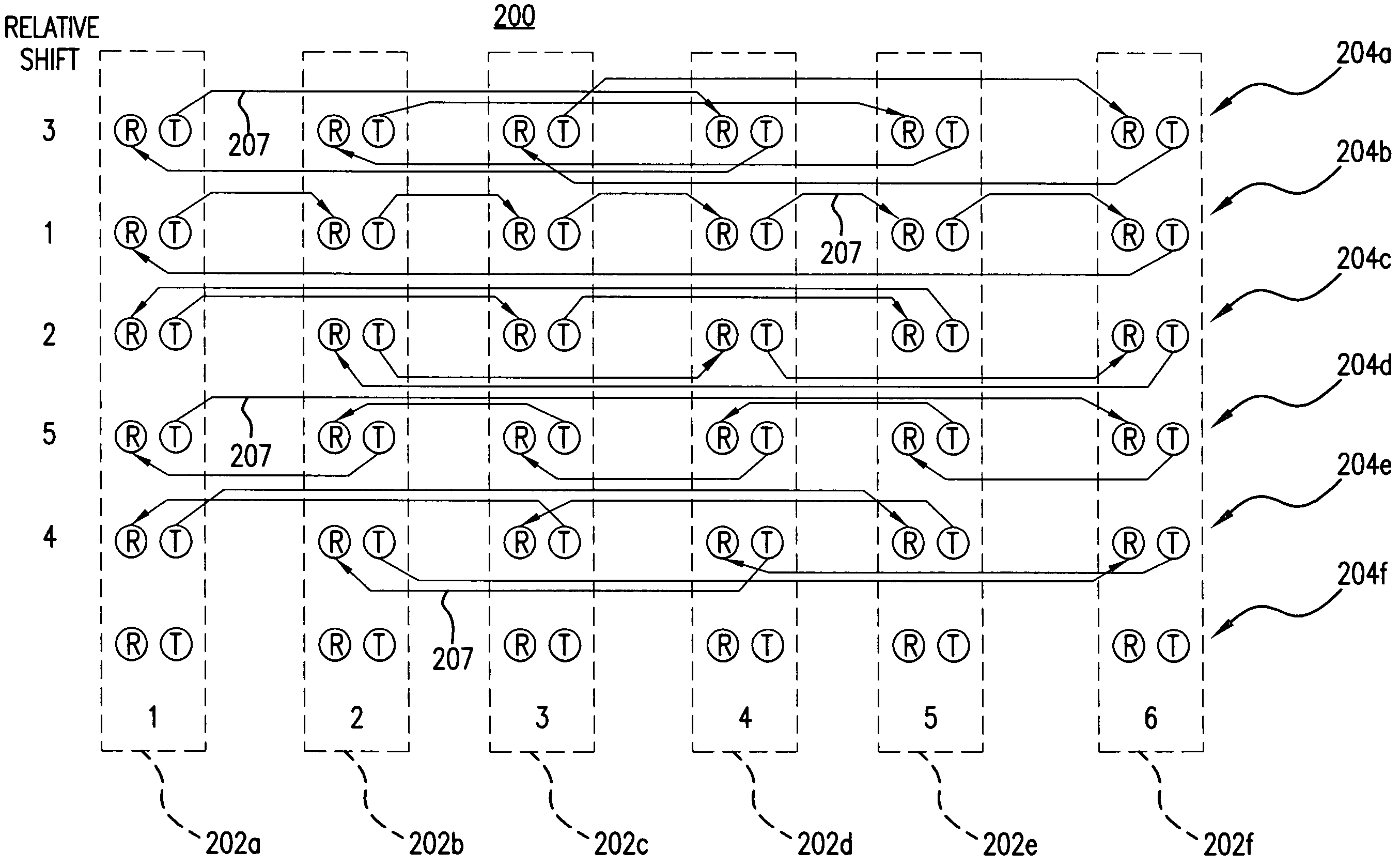
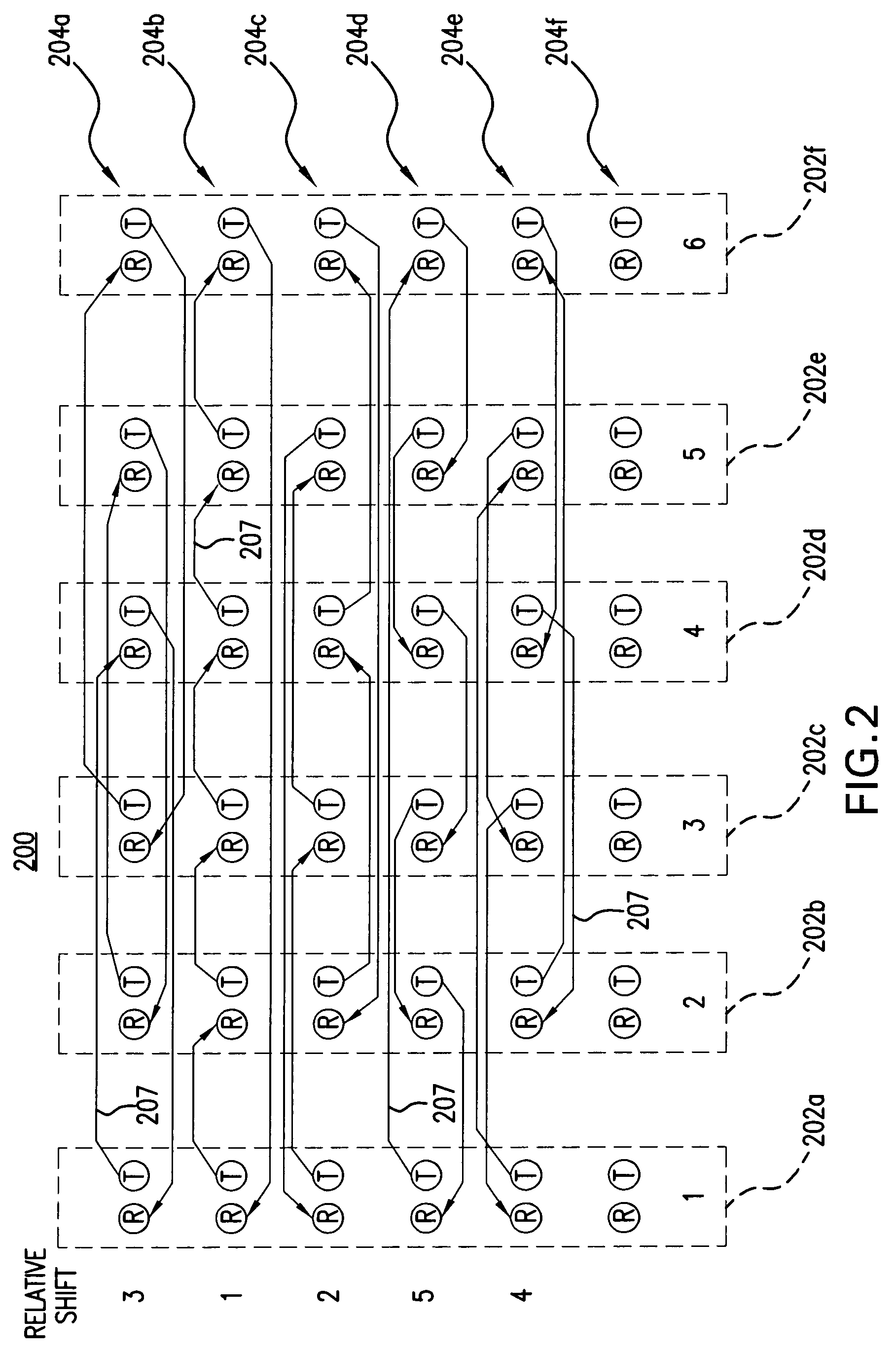
[0018]FIG. 2 is a schematic block diagram of a preferred embodiment of a backplane system 200 in accordance with the present invention. Backplane system 200 includes six slots 202a–f. Each slot has six rows of connections 204a–f. A plurality of traces 207 interconnect the rows of connections. Each row 204 of each slot 202 includes two connections: one for receiving labeled “R” and one for transmitting, labeled “T.” As described above with respect to FIG. 1, “T” and “R” may both represent differential pairs.

[0019]Backplane system 200 is configured to form a full mesh. That is, each slot has a connection to every other slot. More specifically, a transmit / receive pair is provided for each slot to connect to every other slot. Five sets or rows of connections 204a–e are used to interconnect the six slots 202 in a full mesh. The sixth row of connections may be used for signals not required for the mesh. Notably, backplane system 200 does not have an area of congestion such as that between...


PUM


Abstract

A novel backplane routing and configuration (200) supports a full mesh architecture. In this novel configuration, a circuit pack determines which backplane signals to use for a transmission based on the relative distance across the backplane between the board sending the communication and the board receiving the communication. Boards sending the same relative distance use the same rows of signals (204). That is, each row associated with the meshed interconnection is assigned a relative shift or distance for a connection. The rows (204) that represent a greater relative distance for shift between boards are intermixed next to rows (204) that have a relatively short distance between shifts or boards. In this manner, the number of layers required is minimized and the utilization of routing channels is optimized. In particular, for a N slot backplane with one routing channel between rows, (N / 2+1) layers are required, rather than N layers. And, vertical routing is not required.

Description

FIELD OF THE INVENTION[0001]The present invention generally relates to large electronic systems, and in particular, to a backplane configuration with shortest-path, relative-shift routing.BACKGROUND OF THE INVENTION[0002]Large electronic systems, as used in computing, data networking, and telecommunications elements, often use a common backplane to provide high speed interconnection between several circuit boards, packs or modules that plug into slots in the backplane. The backplane is typically constructed of a multi-layer circuit board with conductive traces selectively routed to provide the high-speed interconnection. Connectors are provided on the backplane to couple circuit boards, packs, or modules which are held in place using a slotted chassis. The properties of these backplanes often have large influence over the capacity, performance, reliability, cost, and scale properties of electronic systems. Some backplane designs provide high capacity, while others provide low cost.[...

Claims


Application Information

Patent Timeline
Patent Type & Authority Patents(United States)
IPC IPC(8): G06F13/00H05K1/00H05K7/14
CPCH05K1/0296H05K7/1459H05K2201/044H05K2201/09236
Inventor BYERS, CHARLES CALVINNOVOTNY, ROBERT ALLEN
Owner LUCENT TECH INC
Why Eureka
Try Eureka