Decoding a received BCH encoded signal
- Summary
- Abstract
- Description
- Claims
- Application Information
AI Technical Summary
Benefits of technology
Problems solved by technology
Method used
Image
Examples
Embodiment Construction
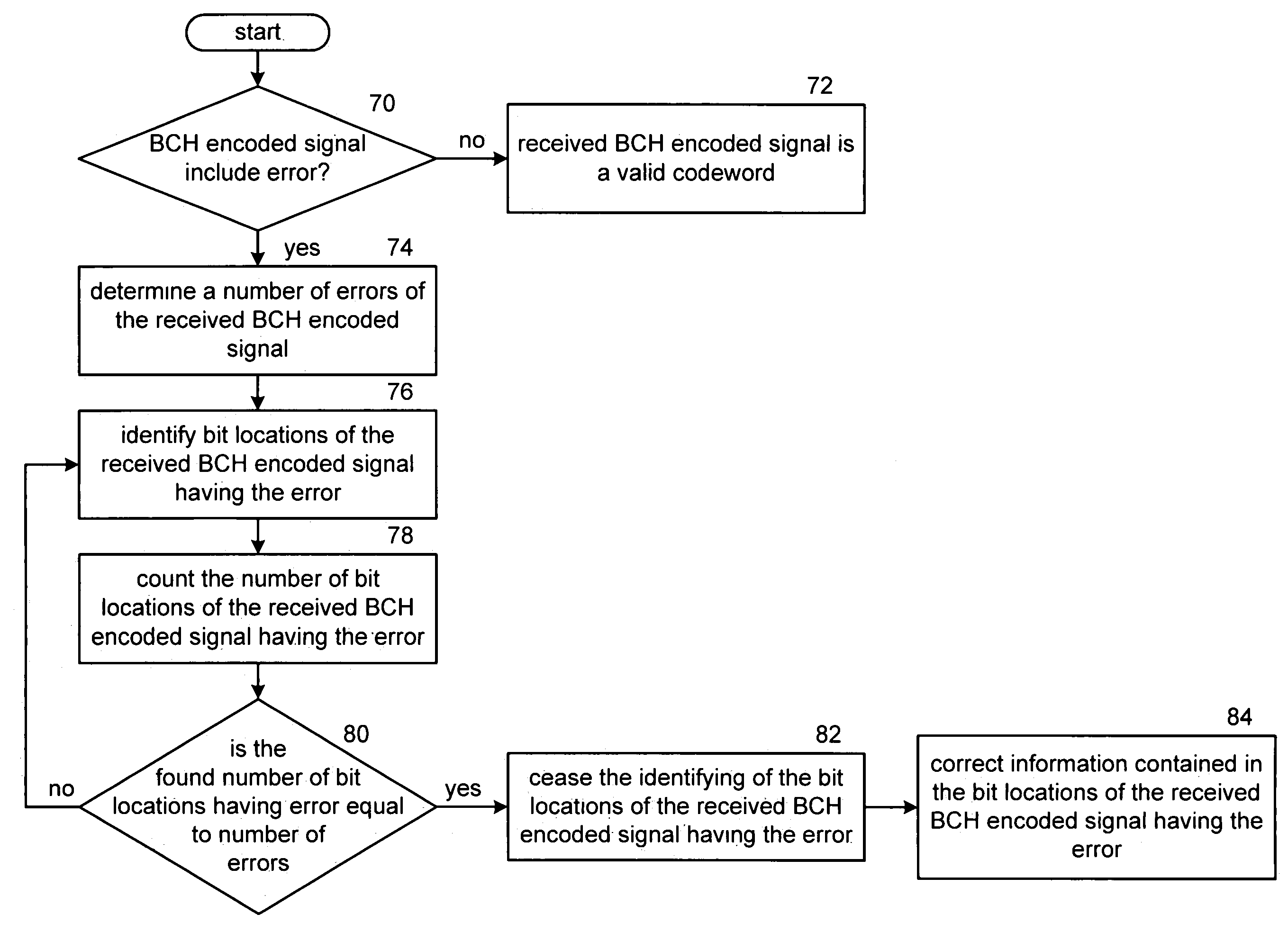
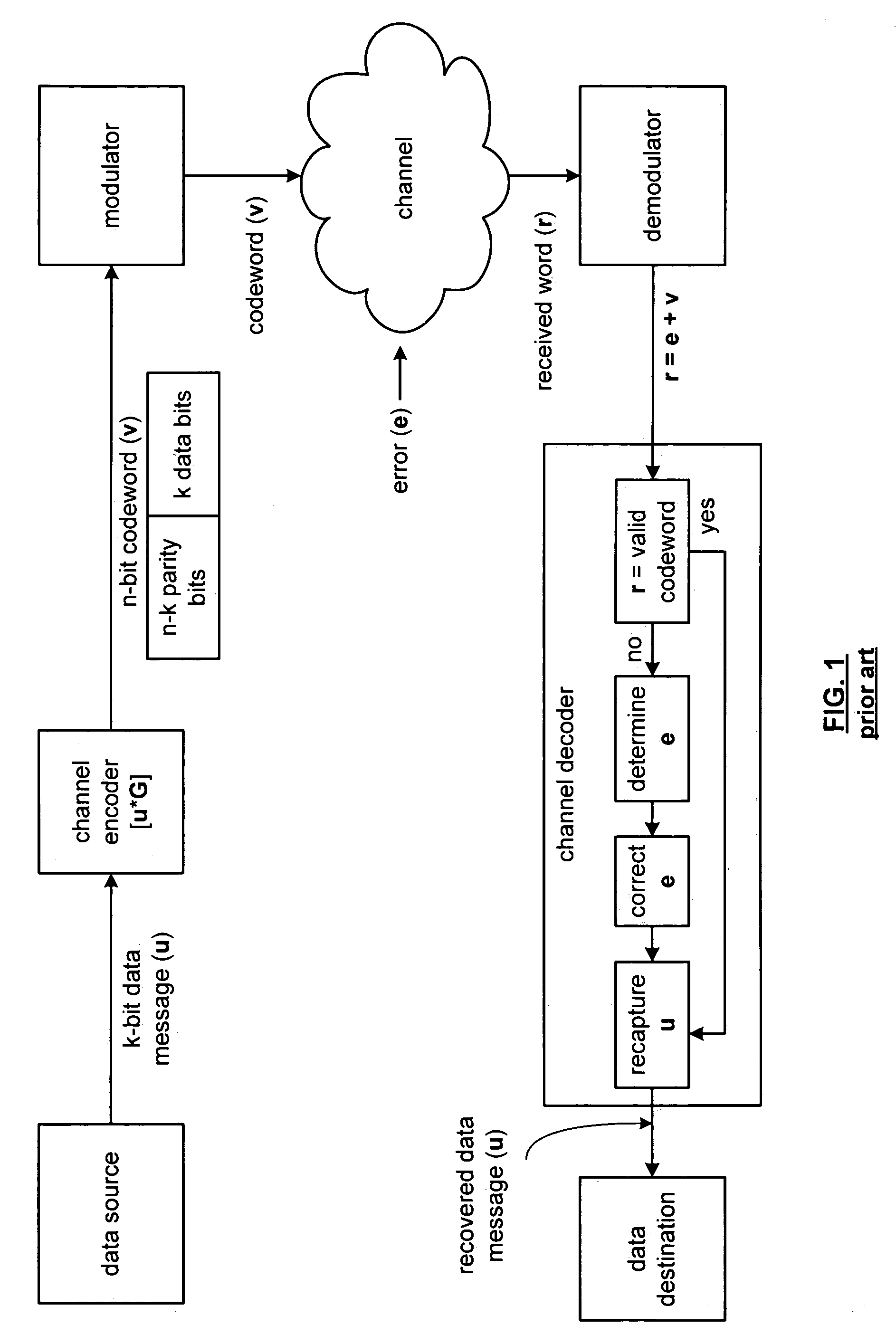
[0049]FIG. 10 is a schematic block diagram of a BCH decoder 10 that includes an interface 12, an error determination module 14, a bit location of error determination module 16, an error correction module 18, a number of error determination module 20, an error bit count module 22, and a comparator 24. The interface 12, which may include a demodulator, receives a BCH encoded signal 26 in a polynomial format. In general, the received polynomial BCH encoded signal 26 is r(x)=r0x0+r1X1+r2x2+r3x3+ . . . +rn−1xn−1, with the highest order term generally being received first. The interface 12 provides the received signal 26 to the error determination module 14 and to the error correction module 18.
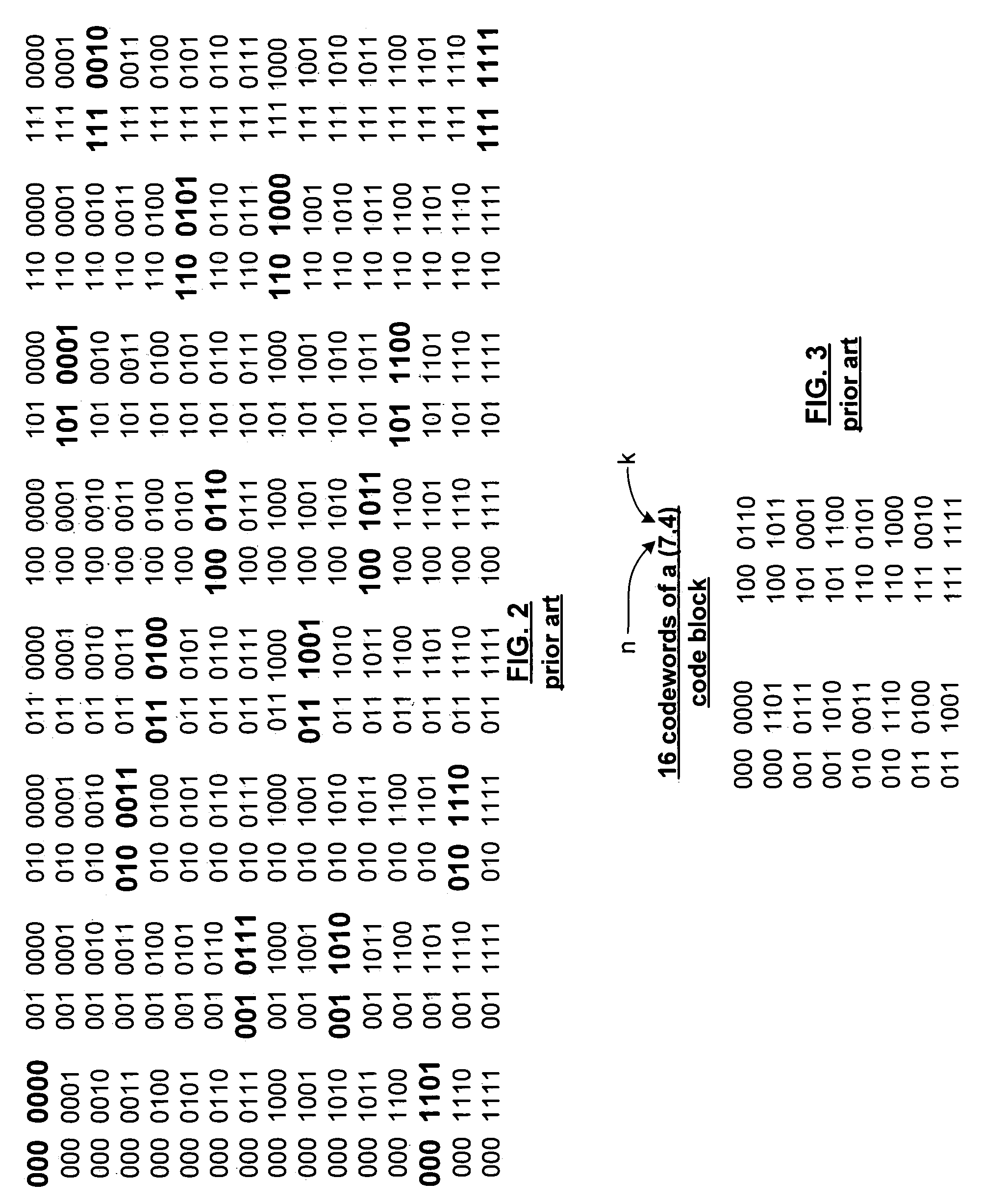
[0050]The error determination module 14 interprets the received signal 26 to determine if it is a valid codeword for the given code block. For example, if the code block is a (7, 4) code block (where n=7 and indicates the number of bits in the codeword and k=4 and indicates the number of bits in th...
PUM
 Abstract
Description
Claims
Application Information
 - R&D
- Intellectual Property
- Life Sciences
- Materials
- Tech Scout
- Unparalleled Data Quality
- Higher Quality Content
- 60% Fewer Hallucinations
Browse by: Latest US Patents, China's latest patents, Technical Efficacy Thesaurus, Application Domain, Technology Topic, Popular Technical Reports.
© 2025 PatSnap. All rights reserved.Legal|Privacy policy|Modern Slavery Act Transparency Statement|Sitemap|About US| Contact US: help@patsnap.com


