System, method and apparatus for petrophysical and geophysical measurements at the drilling bit

a technology of petrophysical and geophysical measurements and drilling bit, which is applied in the direction of surveying, directional drilling, and well accessories, etc., can solve the problems of insufficient quality and resolution, limited compatibility of mud motors with other drill string components, and significant sections of horizontal boreholes intended to be placed in productive zones may be rendered useless. , to achieve the effect of high resolution

Active Publication Date: 2007-04-24
HALLIBURTON ENERGY SERVICES INC
View PDF19 Cites 45 Cited by
  • Summary
  • Abstract
  • Description
  • Claims
  • Application Information

AI Technical Summary

Benefits of technology

[0026]A technical advantage of the present invention is the production of high resolution formation images proximate to the bottom (end) of the bottom hole assembly (BHA) while drilling the borehole. Another technical advantage is the taking of imaging data proximate to the bit reduces to a minimum the time between the actual cutting of a rock in the borehole and the measurement of one or more properties of the borehole wall, thus enabling nearly immediate response, in terms of changes in drilling practices, to changes in the formation that is being drilled. Another technical advantage is the design of standard inserts for mounting in the long gauge portion of the bit and sensors for mounting in the flutes of the long gauge. A basic insert and sensor template may be specified which may accommodate many of the standard bit designs.

Problems solved by technology

As the tools rotate in the borehole, the data from them reflect these formation variations, and can be very important in “geo-steering”—that is, in the process of drilling a highly deviated or horizontal well bore through a formation, because the seismic data which are initially used to target a formation are often of insufficient quality and resolution to accurately place the well bore to the satisfaction of the driller.
In this manner significant sections of horizontal boreholes intended to be placed in productive zones may be rendered useless.
A disadvantage of the former approach is the difficulty of doing this without designing the sensor directly into the mud motor assembly, which limits the compatibility of the mud motors with other drill string components.
Alternatively, designing sensors in the bit presents a similar problem in that constraints are placed on the choice of bits if the sensors are placed there.
Even if the placement of the hole is correct, the spiral sections so produced cause problems with placement of casing, and thereby limit the length of producing hole that can be obtained.
In contrast with wireline logging, reliable wall contact is usually not available in LWD logging.
Although sensors that require wall contact are available in the LWD logging—density tools are an example—wall contact is intermittent, and a great deal of effort is expended to compensate for this fact.
Images are produced with such tools, but these are necessarily of low resolution because of the physics of the sensor and the lack of reliable contact with the borehole wall.

Method used


Image

  • System, method and apparatus for petrophysical and geophysical measurements at the drilling bit
  • System, method and apparatus for petrophysical and geophysical measurements at the drilling bit
  • System, method and apparatus for petrophysical and geophysical measurements at the drilling bit

Examples


Embodiment Construction

[0036]Referring now to the drawings, the details of exemplary embodiments of the present invention are schematically illustrated. Like elements in the drawing will be represented by like numbers, and similar elements will be represented by like numbers with a different lower case letter suffix.

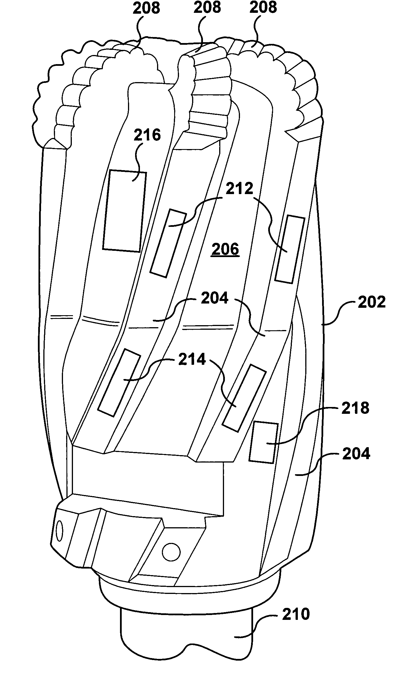
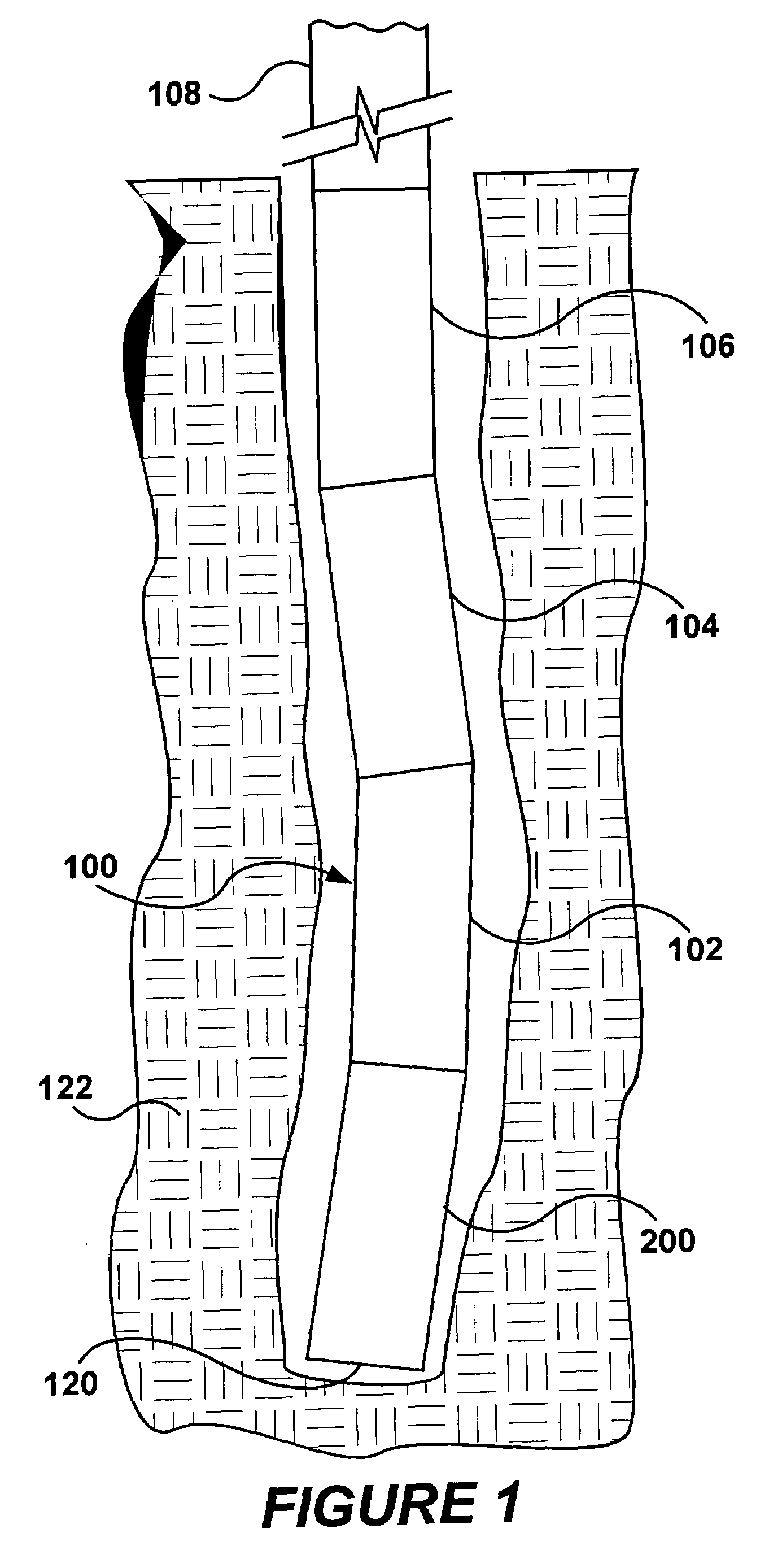
[0037]Referring to FIG. 1, depicted is a bottom hole assembly (BHA). The BHA, generally represented by the numeral 100, is used for drilling a borehole (or wellbore) 120 through underground formations 122. A typical BHA 100 includes a long gauge drill bit 200 for drilling the wellbore 120, a bend section 102, a downhole motor or turbine 104, a logging-while-drilling (LWD) tool 106, and drill string 108 which goes to the surface and connects to a drilling rig (not shown). Other configurations for the BHA 100 are possible and are contemplated to be used with the present invention. For a more detailed description of a steerable drilling system that the present invention may be beneficially used w...


PUM


Abstract

Measurement of petrophysical and geophysical data of formations in a wellbore using a long gauge bit having at least one sensor therewith. The at least one sensor may be installed in at least one flute of the long gauge bit and / or in the long gauge portion thereof. Data for creating images of the formations are obtained at or near the bottom of the borehole and proximate to the long gauge bit used for drilling the borehole. Orientation of the long gauge bit is also available on a real time basis. Magnetic and / or gravitational sensors may be used in determining bit orientation. The flutes of the long gauge bit and the long gauge portion thereof may have standard inserts to accommodate various types of different sensors and electronic packages therefor.

Description

FIELD OF THE INVENTION[0001]The present invention relates generally to a system and method, using a bottom hole assembly, for obtaining formation data and locations thereof in a wellbore for creating images thereof, and more particularly to obtaining the formation data and locations thereof with sensors located in a long gauge drill bit attached to the bottom hole assembly.BACKGROUND OF THE INVENTION TECHNOLOGY[0002]Logging while drilling (LWD) measurements, while initially conceived primarily as alternatives or replacements for similar wireline measurements, are increasingly used to provide information which can influence the drilling process. This has progressed from determining the optimum casing point near an overpressured zone, to using gamma ray or density measurements to place and maintain a borehole within a geologic zone. In the latter case a number of different tools can be used, two examples of which are so-called azimuthal natural gamma ray tools and azimuthal density to...

Claims


Application Information

Patent Timeline
Patent Type & Authority Patents(United States)
IPC IPC(8): E21B47/00E21B7/06E21B45/00E21B47/022
CPCE21B7/067E21B45/00E21B47/0002E21B47/01E21B47/022G01V11/00G01V2210/6163G01V2210/6165G01V2210/6167E21B47/002E21B47/013E21B47/0025
Inventor SPROSS, RONALD L.RODNEY, PAUL F.
Owner HALLIBURTON ENERGY SERVICES INC
Why Eureka
Try Eureka