Layered modulation for digital signals

Inactive Publication Date: 2007-04-24
THE DIRECTV GROUP
View PDF150 Cites 81 Cited by
  • Summary
  • Abstract
  • Description
  • Claims
  • Application Information

AI Technical Summary

Benefits of technology

[0011]In the invention, a second (lower) layer of modulation is added to a first (upper) layer of modulation. Such an approach affords backwards-compatible implementation, i.e. legacy equipment can remain unchanged and continue to transmit and receive signals while new equipment may simultaneously transmit and receive enhanced signals. The addition of the second layer provides increased capacity and services to receivers that can process information from both layers. The upper and lower layer signals may be non-coherent; there is no required carrier phase relationship between the two signal layers.
[0012]Alternate embodiments may abandon backward compatibility with particular legacy equipment. However, layered modulation may still be used to provide expanded services with future system upgrades. Furthermore, as will be readily apparent to those skilled in the art, the principle of the invention may be extended to additional layers of modulation, with independent modulations, forward error correction (FEC) coding and code rates as the system may support in the future, while maintaining backward compatibility. The present invention provides many advantages.
[0013]For example, spectral efficiency may be significantly increased while maintaining backward compatibility with pre-existing receivers; if both layers use the same modulation with the same code rate, the spectral efficiency may be dou

Problems solved by technology

However, it is more difficult to implement either improvement in old systems and new services when it is necessary to replace existing legacy hardware, such as transmitters and receivers.
In the realm of wireless communications, this principle is further highlight

Method used


Image

  • Layered modulation for digital signals
  • Layered modulation for digital signals
  • Layered modulation for digital signals

Examples


Embodiment Construction

[0023]In the following description, reference is made to the accompanying drawings which form a part hereof, and which show, by way of illustration, several embodiments of the present invention. It is understood that other embodiments may be utilized and structural changes may be made without departing from the scope of the present invention.

Overview

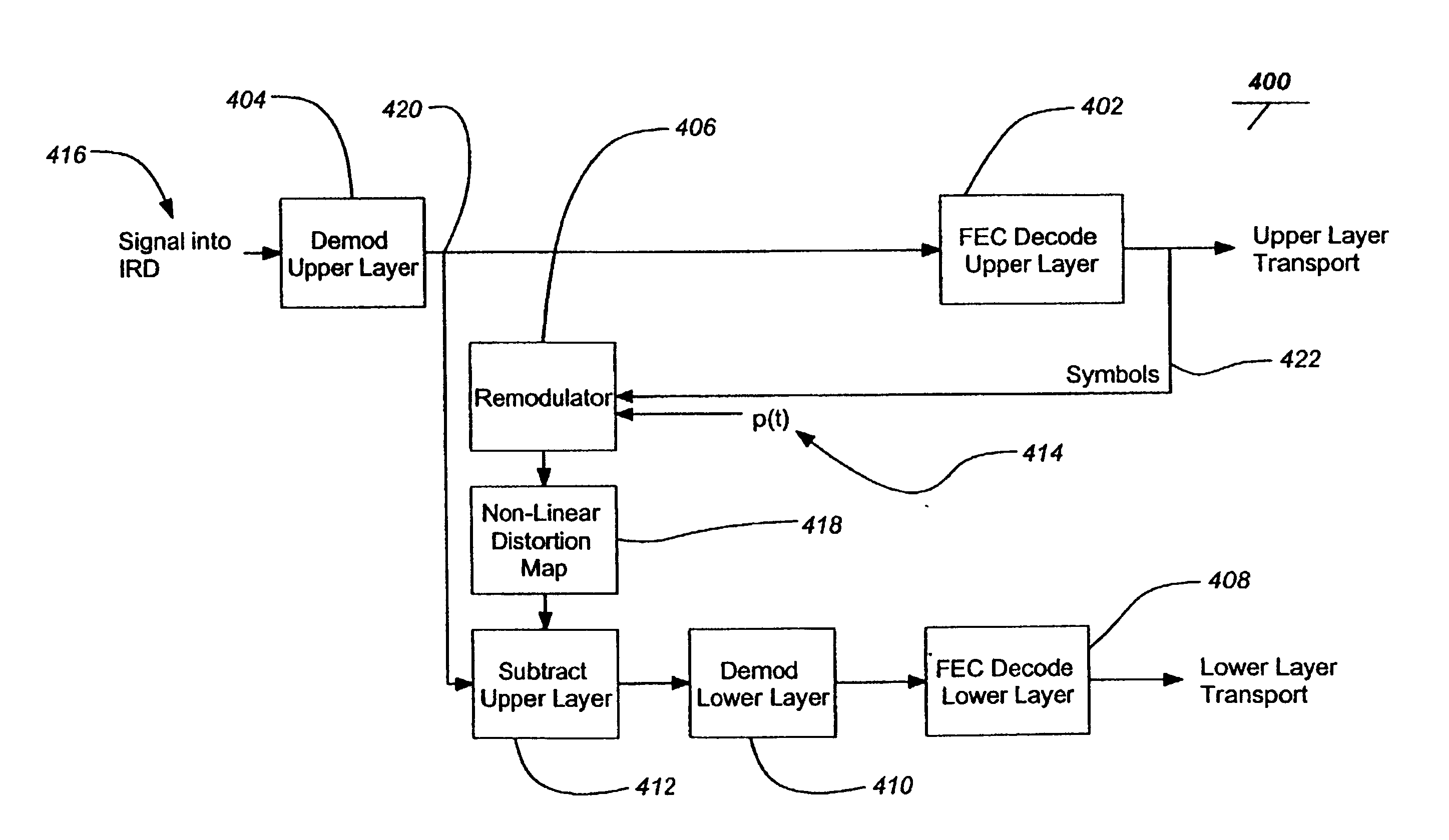
[0024]The present invention provides for the modulation of signals at different power levels and advantageously for the signals to be non-coherent from each layer. In addition, independent modulation and coding of the signals may be performed. Backwards compatibility with legacy receivers, such as a quadrature phase shift keying (QPSK) receiver is enabled and new services are provided to new receivers. A typical new receiver of the present invention uses two demodulators and one remodulator as will be described in detail hereafter.

[0025]In a typical backwards-compatible embodiment of the present invention, the legacy QPSK signal is boost...


PUM


Abstract

Signals, systems and methods for transmitting and receiving layered modulation for digital signals are presented. A layered signal for transmitting data, comprises a first signal layer including a first carrier and first signal symbols for a first digital signal transmission and a second signal layer including a second carrier and second signal symbols for a second signal, transmission disposed on the first signal layer, wherein the layered signal has the first carrier demodulated and first layer decoded to produce the first signal symbols for a first layer transport, the first signal symbols are remodulated and subtracted from the layered signal to produce the second signal layer, and the second signal layer has the second carrier demodulated and decoded to produce the second signal symbols for a second layer transport.

Description

BACKGROUND OF THE INVENTION[0001]1. Field of the Invention[0002]The present invention relates generally to systems for transmitting and receiving digital signals, and in particular, to systems for broadcasting and receiving layered modulation in digital signals.[0003]2. Description of the Related Art[0004]Digital signal communication systems have been used in various fields, including digital TV signal transmission, either terrestrial or satellite.[0005]As the various digital signal communication systems and services evolve, there is a burgeoning demand for increased data throughput and added services. However, it is more difficult to implement either improvement in old systems and new services when it is necessary to replace existing legacy hardware, such as transmitters and receivers. New systems and services are advantaged when they can utilize existing legacy hardware. In the realm of wireless communications, this principle is further highlighted by the limited availability of e...

Claims


Application Information

Patent Timeline
IPC IPC(8): H04L27/04H03F1/32H03F3/58H04B7/185H04B17/00H04L27/36
CPCH03F1/32H03F3/58H04B7/18515H04H20/103H04H20/42H04B17/318H04L1/20H04L27/183H04L27/227H04L27/366H04H60/07H03F2200/393H04L2027/0061H04J11/004H04L27/3488
Inventor CHEN, ERNEST C.
Owner THE DIRECTV GROUP
Why Eureka
Try Eureka