Communication system employing turbo codes and a hybrid automatic repeat request scheme

Active Publication Date: 2007-04-24
WIPRO LTD
View PDF9 Cites 19 Cited by
  • Summary
  • Abstract
  • Description
  • Claims
  • Application Information

AI Technical Summary

Benefits of technology

[0015]As demonstrated below by simulation, the present proposal achieves a better perf

Problems solved by technology

Meanwhile, IR is much more complex in terms of memory, processing, and signalling requirements.
This scheme is quite complex as it employs block interleaving and BMP to generate different IR redu

Method used


Image

  • Communication system employing turbo codes and a hybrid automatic repeat request scheme
  • Communication system employing turbo codes and a hybrid automatic repeat request scheme
  • Communication system employing turbo codes and a hybrid automatic repeat request scheme

Examples


first embodiment

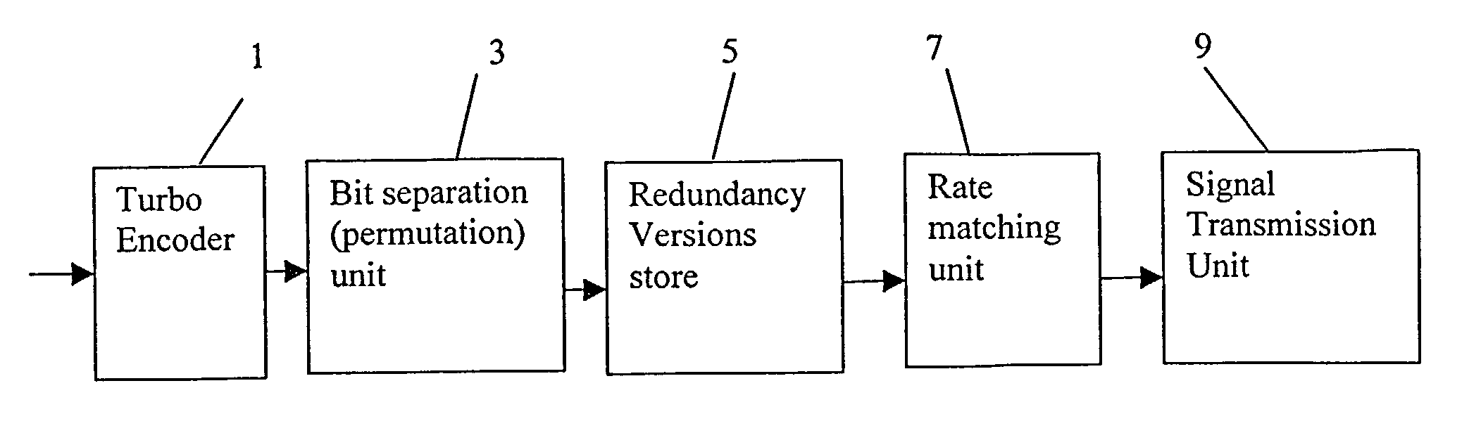
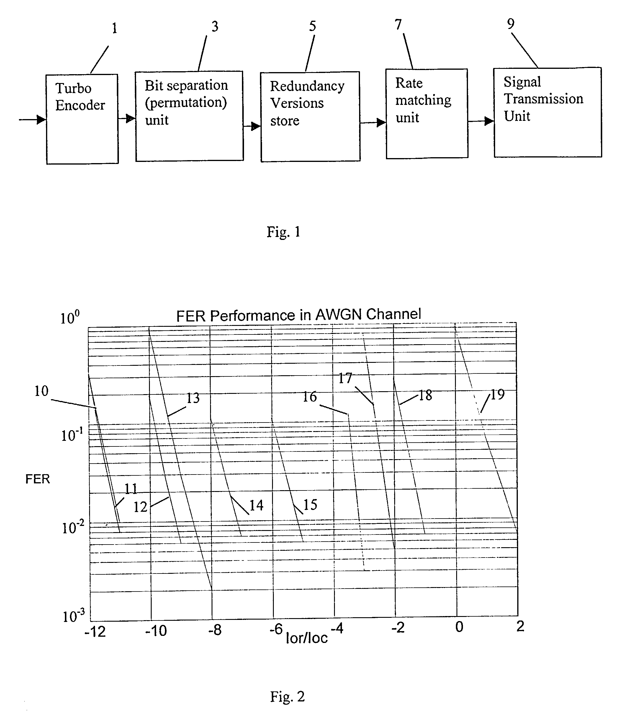
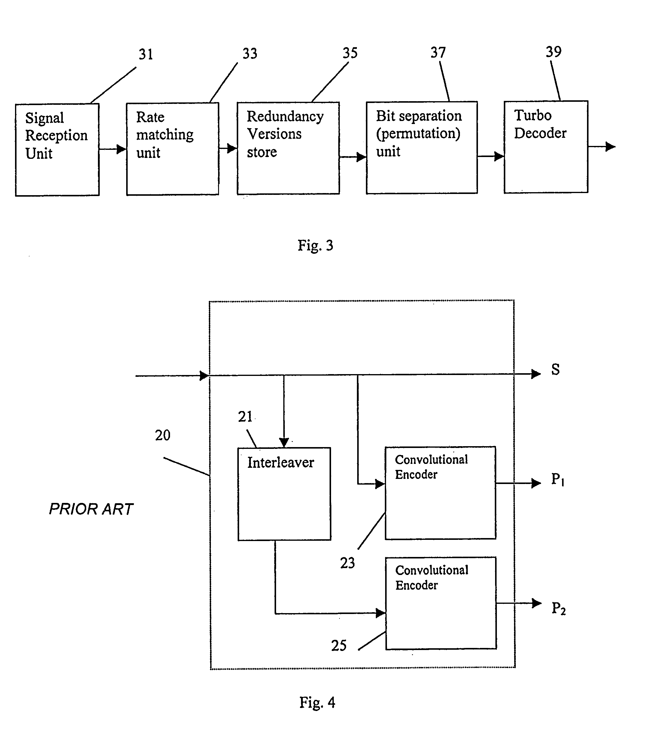
[0043]As the invention, consider a wideband code division multiple access (WCDMA) communication system using Turbo codes with coding rate of ⅓. Five modulation and coding schemes (MCS) are supported by this system. These are QPSK with coding rate of ¼, QPSK with coding rate of ½, QPSK with coding rate of ¾, 16QAM with coding rate of ½ and 16QAM with coding rate of ¾. Rate matching (puncturing or repetition) is employed to adjust the coding rates. As explained above with reference to FIG. 3, the output of the turbo encoder 1 is represented as (S, P1, P2). We refer to this encoded signal as “version 1”. The rate matching unit 5 is arranged, upon receiving this encoded signal to transmit the systematic bits and repeat or puncture the parity bits to get the desired coding.

[0044]Within the embodiment, the permutation unit 3 produces a further three redundancy versions:[0045]Version 2, (P1, P2, S). In this version, all the parity bits P1 will be transmitted and parity bits P2 and the syst...

second embodiment

[0062]The operation of the second embodiment is as follows:

[0063]As in the first embodiment, version 1 is initially transmitted from the redundancy version store 5 to the rate matching unit 7. The result is transmitted to the transmission unit 9 which produces a first transmission.

[0064]In the case that the receiver is performing Chase combining, if no acknowledgement (NACK) is received after the initial transmission, then the first version is sent again to the rate matching unit 7, and the result is retransmitted as a second transmission by the transmission unit 9. If NACK is received again, then the first version is sent again to the rate matching unit 7, and the result is retransmitted as a third transmission by the transmission unit 9.

[0065]By contrast, considering the case that IR in the receiver is desired, then following the first NACK, version 2 is transmitted to the rate matching unit 7, to produce a second transmission by the transmission unit 9. Following a further NACK, ...

third embodiment

[0067]We now turn to the invention. Again, the structure of the transmitter is as shown in FIG. 1, but in this case an encoder 1 is used having a coding rate of ⅕. Therefore, the output of Turbo encoder can be described as (S, P1, P2, P3, P4), where P3 and P4 are the two further parity bit streams. Suppose that the required coding rates for the transmissions are ¼, ½ and ⅓. Based on our invention, five IR redundancy versions can be constructed as follows:[0068]Version 1, (S, P1, P2, P3, P4). Upon receiving this version, the rate matching unit 7 is arranged to transmit all the systematic bits, and to puncture the parity bits P1, P2, P3, and P4 to get the desired coding rate for transmission;[0069]Version 2, (P1, P2, P3, P4, S). For this version, the rate matching unit 7 will arrange that all the parity bits P1 will be transmitted and parity bits P2, P3, P4 and the systematic bits S will be punctured to get the desired coding rate for transmission;[0070]Version 3, (P2, P3, P4, S, P1)....


PUM


Abstract

A communications system employs a HARQ method and, for at least some transmission formats, incremental redundancy (IR) signals. For such formats, the multiple IR signals are derived from a single turbo encoded signal by forming multiple permutations of the encoded signal. The permutations are then converted to the coding rate of the selected transmission format. It is demonstrated by simulation that the present proposal achieves a better performance than the known HARQ techniques, while its implementation is simpler. For certain transmission formats, the transmitted signal in response to a retransmission request is identical to the first transmitted signal.

Description

FIELD OF THE INVENTION[0001]The present invention relates to a communication system which operates a hybrid automatic repeat request (HARQ) scheme. The invention further relates to the methods of signal transmission and reception performed by the communication system, and to transmitters and receivers within the system.BACKGROUND OF THE INVENTION[0002]Many communication systems can be generally described as including a first unit (transmitter) which is to send a message to a second unit (a receiver). Frequently, the transmitter includes an encoder for using the message to generate a signal which is actually transmitted, and the receiver includes a corresponding decoder for reconstructing the message from the signal.[0003]Recently turbo codes have become widely used in such communication systems. FIG. 4 shows schematically the structure of an encoder 20 used to produce a turbo code signal with a coding rate (i.e. the ratio of the number of bits of the message input to the encoder to ...

Claims


Application Information

Patent Timeline
IPC IPC(8): H03M13/00H04L1/18H03M13/27H03M13/29H03M13/35H04L1/00
CPCH03M13/27H03M13/2957H03M13/35H03M13/6306H03M13/6362H04L1/005H04L1/0069H04L1/1819
Inventor XU, CHANG QINGPAN, JU YANKATSURAGAWA, HIROSHI
Owner WIPRO LTD
Why Eureka
Try Eureka