

Feed adaptation core drill
- Summary
- Abstract
- Description
- Claims
- Application Information
AI Technical Summary
Benefits of technology
Problems solved by technology
Method used
Image

Examples
Embodiment Construction
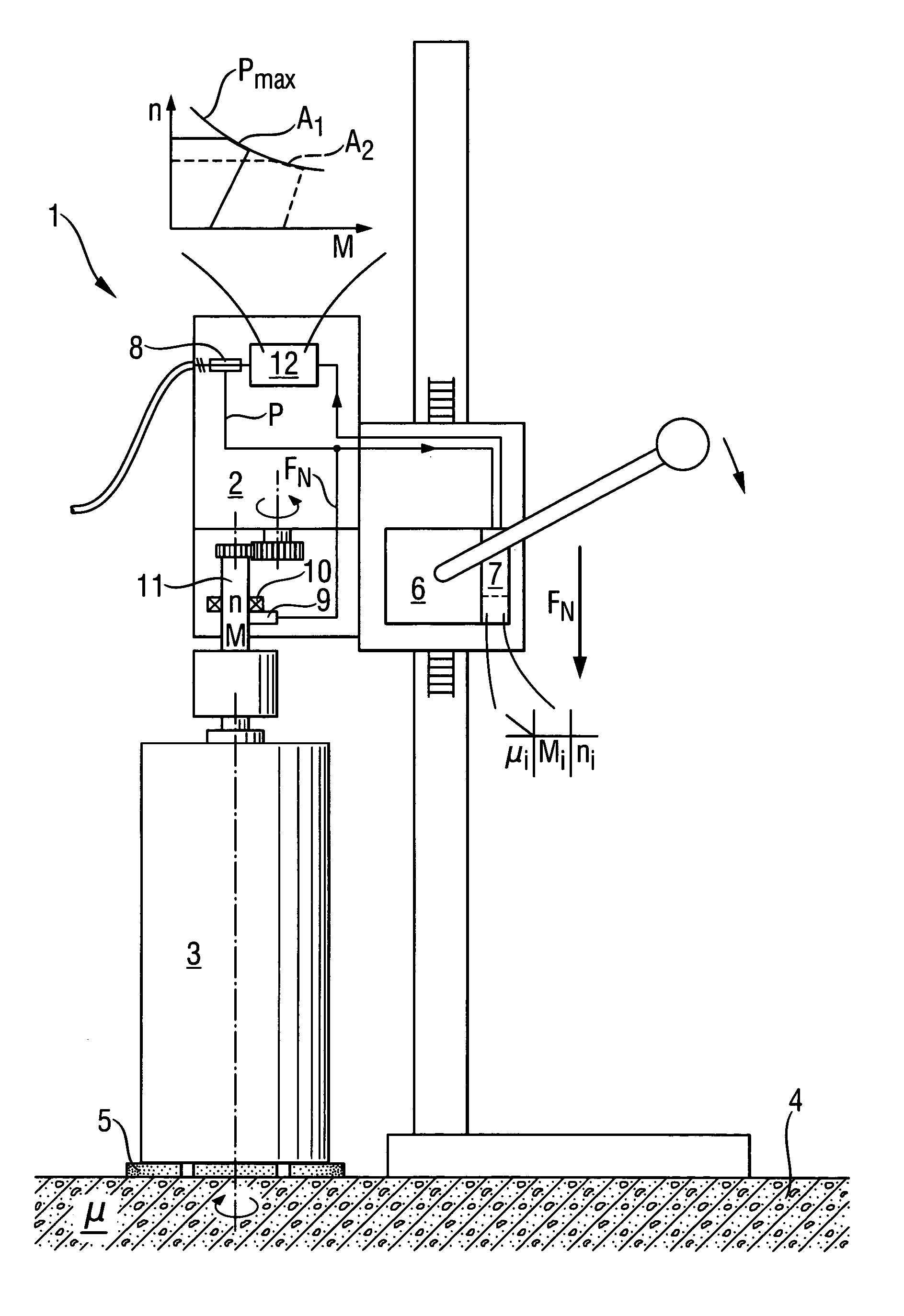
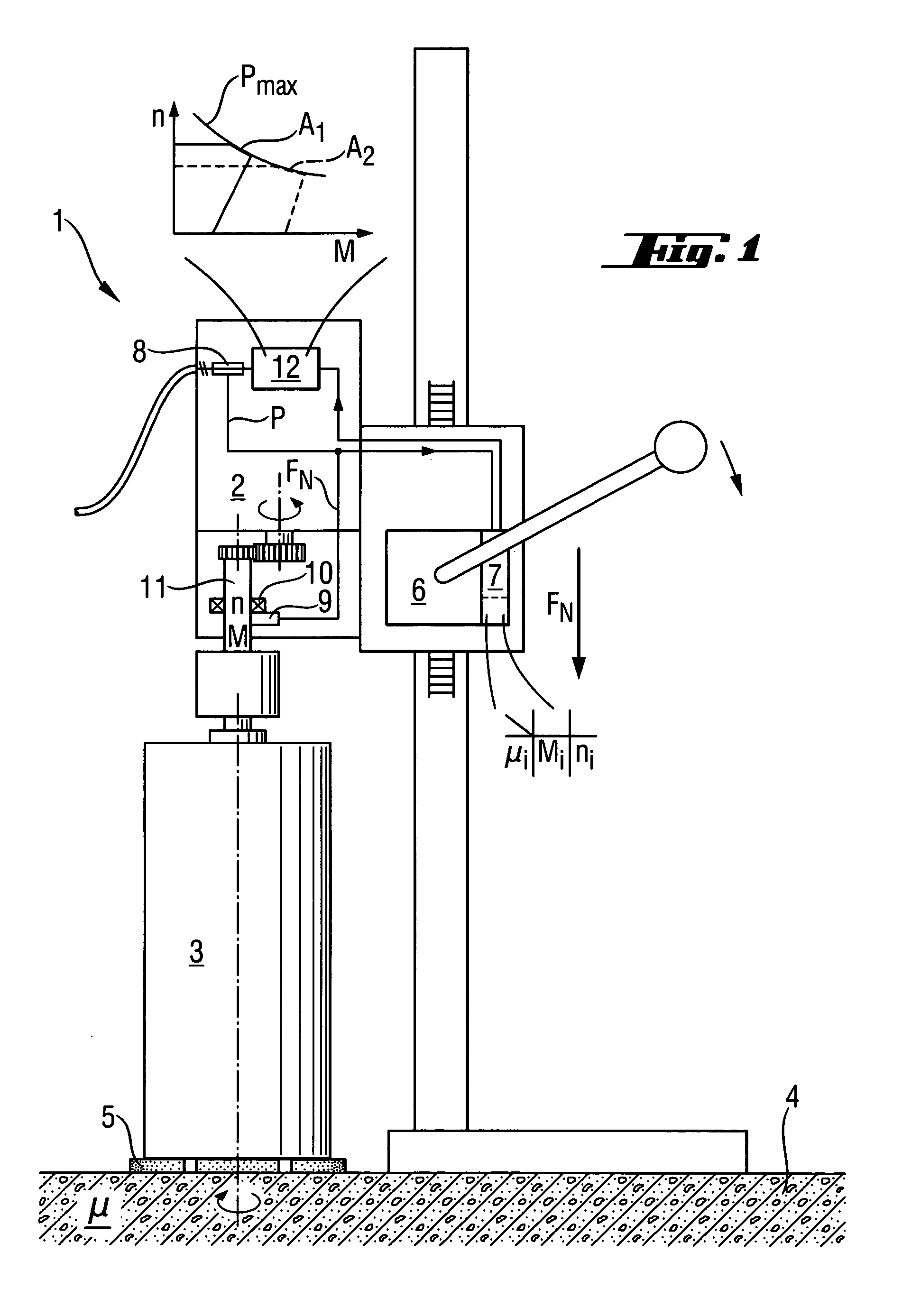
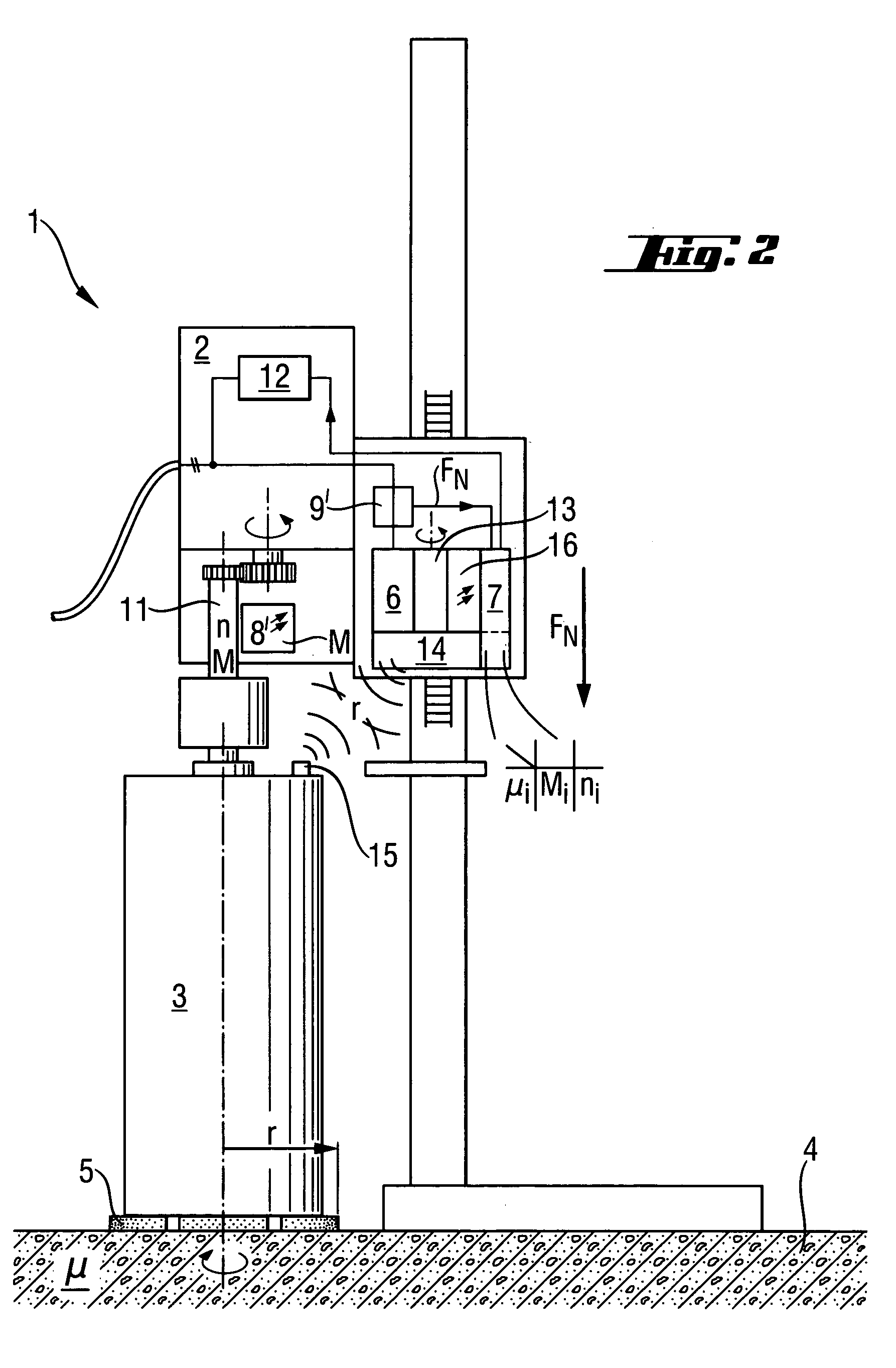
[0022]According to FIG. 1, a core drilling machine 1 has an electrical motor 2 for rotationally driving a core drill bit 3 with ultrahard cutting edges 5 that are oriented axially to a work piece 4 and a feeding means 6 having a controller 7 for controlling the feed of the core drill bit 3 against the work piece 4. The control is effected depending on a control parameter one-to-one with the substrate-specific frictional coefficient μ, which is determined by the controller 7 from an electrical power P detected using a sensor 8 in the current path of the electrical motor 2 and from a contact pressing force FN of the core drill bit detected using a force sensor 9. μ=P / (2πn r Fn)=M / (r FN), with μ: frictional coefficient: P: power consumption; M: torque; FN: normal force; r: radius of the drill bit. The force sensor 9 is configured as a piezo force sensor and arranged in a thrust bearing zone 10 of a drive spindle 11 of the core drilling machine 1. In the controller 7 configured as a mic...
PUM
| Property | Measurement | Unit |
|---|---|---|
| Force | aaaaa | aaaaa |
| Speed | aaaaa | aaaaa |
| Torque | aaaaa | aaaaa |
Abstract
Description
Claims
Application Information