
Bookbinding machine

a bookbinding machine and roller chain technology, applied in the field of bookbinding machines, can solve the problems of unaccepted play in the drive link, limited space, and unfavorable use of roller chain sections, and achieve the effect of simple construction and precise positioning operation

Inactive Publication Date: 2007-05-01
KOLBUS
View PDF20 Cites 18 Cited by
  • Summary
  • Abstract
  • Description
  • Claims
  • Application Information

AI Technical Summary

Benefits of technology

[0009]It is an object of the present invention to create a bookbinding machine of the above-mentioned type which makes possible the performance of precise positioning operations in workstations while being of simple construction.
[0011]The mechanically uncoupled workstations are driven by motors, or are driven hydraulically, pneumatically or electromechanically. The drive system is broken up into small partial systems less subject to oscillations. Operations performed by the workstations are carried out markedly more accurately because the position sensing is carried out locally. Electronic controls make adjustment of the machine simpler and more precise. Further, a bookbinding machine according to the invention simplifies the replacement or addition of workstations because the adjustment of the drive connections in relation to the rear edge of the transported inner books is dispensed with. An advantage of the bookbinding machine according to the invention is that work processes dependent on inner-book position, such as side-stitching, punching, gluing, reinforcing, jacket application, etc., take a substantially simpler form. This advantage is characterised, among other benefits, by a smaller installation space requirement.
[0012]A preferred embodiment of the inventive bookbinding machine is provided when all workstations, previously coupled mechanically, are driven independently of the drive of the transport system of the inner-book clamps. The main shaft can thereby be dispensed with. But even partial mechanical uncoupling offers advantages if, for example, workstations are to be used in bookbinding machines which are differently configured with respect to the central drive system.
[0015]The mechanically uncoupled workstations are advantageously designed to be compatible with the timing distances in different bookbinding machines (also referred to as adhesive binders). When used in a bookbinding machine having a given timing (pitch) distance (T) between the inner-book clamps, the workstations are adjustable to this timing distance. The construction of variants with respect to timing distances is rendered superfluous. In addition, the production, storage and preparation for service of these workstations are greatly simplified. It is also advantageous that the workstations are electronically adjustable with respect to the positions or format height of the inner books.

Problems solved by technology

It is, of course, limited by the available space, which is determined by the number of inner-book clamps.
Oscillations of the drive system superimposed on the chain movement, unequally-stretched sections of the roller chain and play in the drive links are not allowed for in determining the position of the inner-book clamp.

Method used


Image

  • Bookbinding machine
  • Bookbinding machine
  • Bookbinding machine

Examples


Embodiment Construction

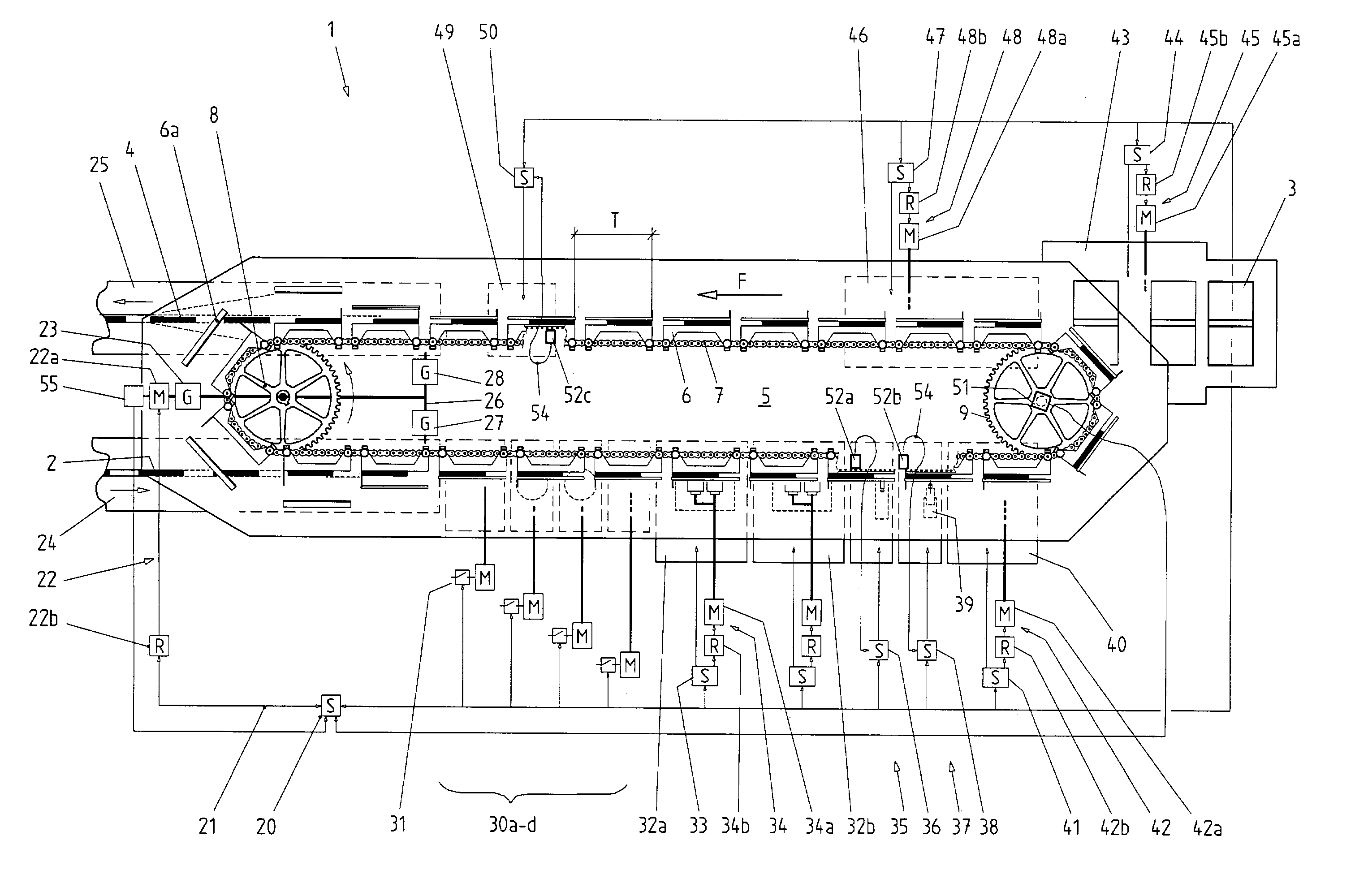
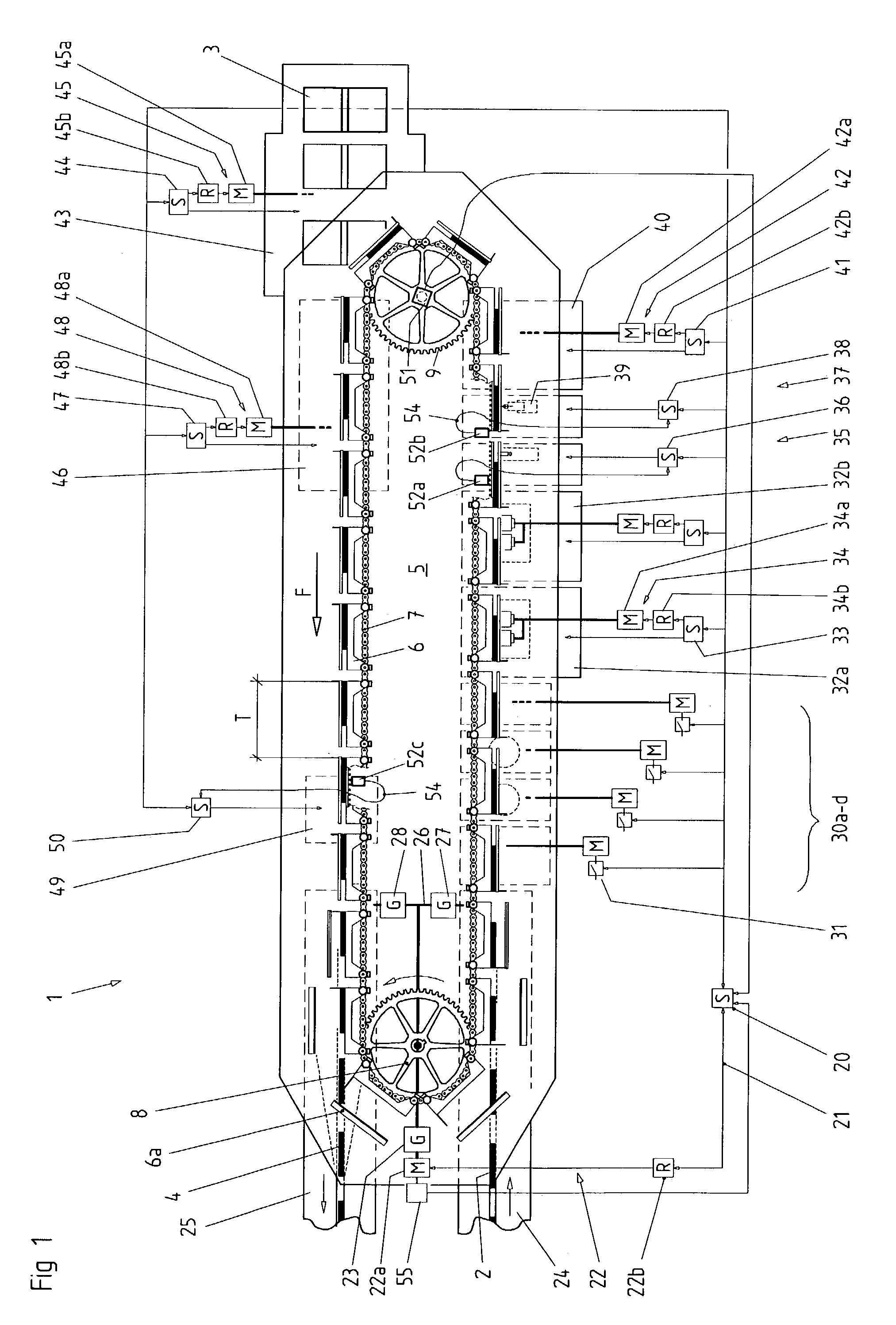
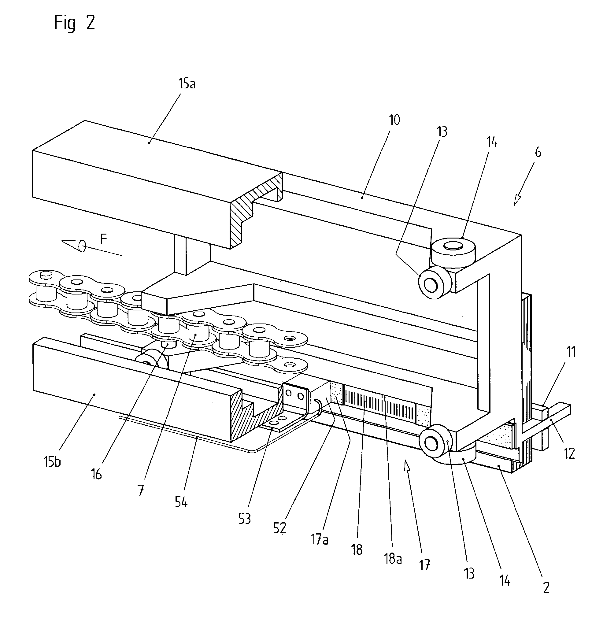
[0019]An exemplary embodiment of a bookbinding machine 1 consists of a transport system 5 having a multiplicity of continuously movable inner-book clamps 6 articulated to a continuous roller chain 7 circulating in a closed track, spine-processing stations 30a–d and workstations 32, 35, 37, 40, 43 and 46 for carrying out positionally precise processing operations. Inner books 2 collated as loose sheets are bound in the bookbinding machine 1 and, in a processing variant, are finished as brochures 4 by the application of a jacket 3. The inner books 2 enter the bookbinding machine 1 while standing on their spines via an intake 24. They are transferred, while being aligned to a rear-edge stop 12, to the inner-book clamps 6 which, starting from an open position 6a, clamp the particular inner book 2 by its lateral faces with an inner jaw 10 and an outer jaw 11 closing relatively thereto. A given portion of the inner book projects downwardly from the inner-book clamp 6 for processing.

[0020]...


PUM


Abstract

A bookbinding machine for processing inner books includes a transport system with a multiplicity of inner-book clamps continually movable in a closed continuous track. Each of the inner book clamps is articulated to a circulating roller chain and has a rear-edge stop for aligning the inner books. The bookbinding machine includes workstations that perform positionally accurate operations on the inner books including the application of glue, the application of reinforcement or gauze sections, the application of jackets, binding with wire stitches, the introduction of utilisation features (e.g. punched holes, tear-off perforations, etc.) and the like. The transport system of the inner-book clamps and at least one workstation are driven independently of one another. A measuring system for positional detection of the inner-book clamps or of the inner books is provided in proximity to the independently driven workstation. The measuring system provides inner book or clamp position data used to control the workstation performing positionally accurate operation on the relevant inner book.

Description

[0001]This application claims the benefit of German Patent Application No. DE 102 21 542.1, filed May 15, 2002.BACKGROUND OF THE INVENTION[0002]1. Field of the Invention[0003]The present invention relates generally to a bookbinding machine and more specifically to a bookbinding machine in which the drives of workstations for performing positionally accurate operations on inner books are not mechanically coupled to the main drive for the book binding machine.[0004]2. Description of the Related Art[0005]A bookbinding machine to which the invention relates is described, for example, in DE 198 46 525 A1 and is also referred to as an adhesive binder having a clamp system. One inner book in each case is clamped by an inner-book clamp while standing on its spine and in this position is transported past various stations. In addition to stations for processing the inner-book spine, such as cutting-off, notching, roughing and brushing, stations are provided for applying adhesive to the spine ...

Claims


Application Information

Patent Timeline
Patent Type & Authority Patents(United States)
IPC IPC(8): B42B5/00B42C9/00B42C19/08
CPCB42C9/0031B42C19/08
Inventor ENGERT, HOLGERGARLICHS, JURGEN
Owner KOLBUS
Learn More