Coupler-multiplexer permutation switch

a permutation switch and multi-function technology, applied in multiplex communication, instruments, optical elements, etc., can solve the problems of imposing a functional burden on the optical network nodes, the use of more complex components, and the common drawbacks of each multi-function transparent optical network node. , to achieve the effect of minimizing the mismatch between the characteristics of the multiplexer and the demultiplexer

Inactive Publication Date: 2007-05-01
THE TRUSTEES OF COLUMBIA UNIV IN THE CITY OF NEW YORK
View PDF6 Cites 11 Cited by
  • Summary
  • Abstract
  • Description
  • Claims
  • Application Information

AI Technical Summary

Benefits of technology

[0020]In yet another embodiment, different permutations in a multiplexing pattern are obtained by electronically controlling the effective-index distribution of the DOS output waveguides. This electronic control is accomplished by using a low driving-voltage device based on a quantum-confined Stark effect (QCSE).
[0021]In still another embodiment, an add / drop multiplexer is integrated with a common grating on a single substrate. This integration minimizes a mismatch between the multiplexer and the demultiplexer characteristics.

Problems solved by technology

In linear optical networks, even more complex components are used because the optical network nodes are required both to broadcast and to route different channels.
The evolution of WDM networks has imposed a functionality burden on the optical network nodes (ONN).
However, this means that the ONNs have to perform many functions in the physical (optical) layer instead of the electronic (logical) layer.
Unfortunately, each of the multi-function transparent optical network nodes known hereto suffer from a common drawback in that they combine individual components, i.e. switches, multiplexers, filters and routers, in a conventional way to perform a specific routing and switching functions.

Method used


Image

  • Coupler-multiplexer permutation switch
  • Coupler-multiplexer permutation switch
  • Coupler-multiplexer permutation switch

Examples


Embodiment Construction

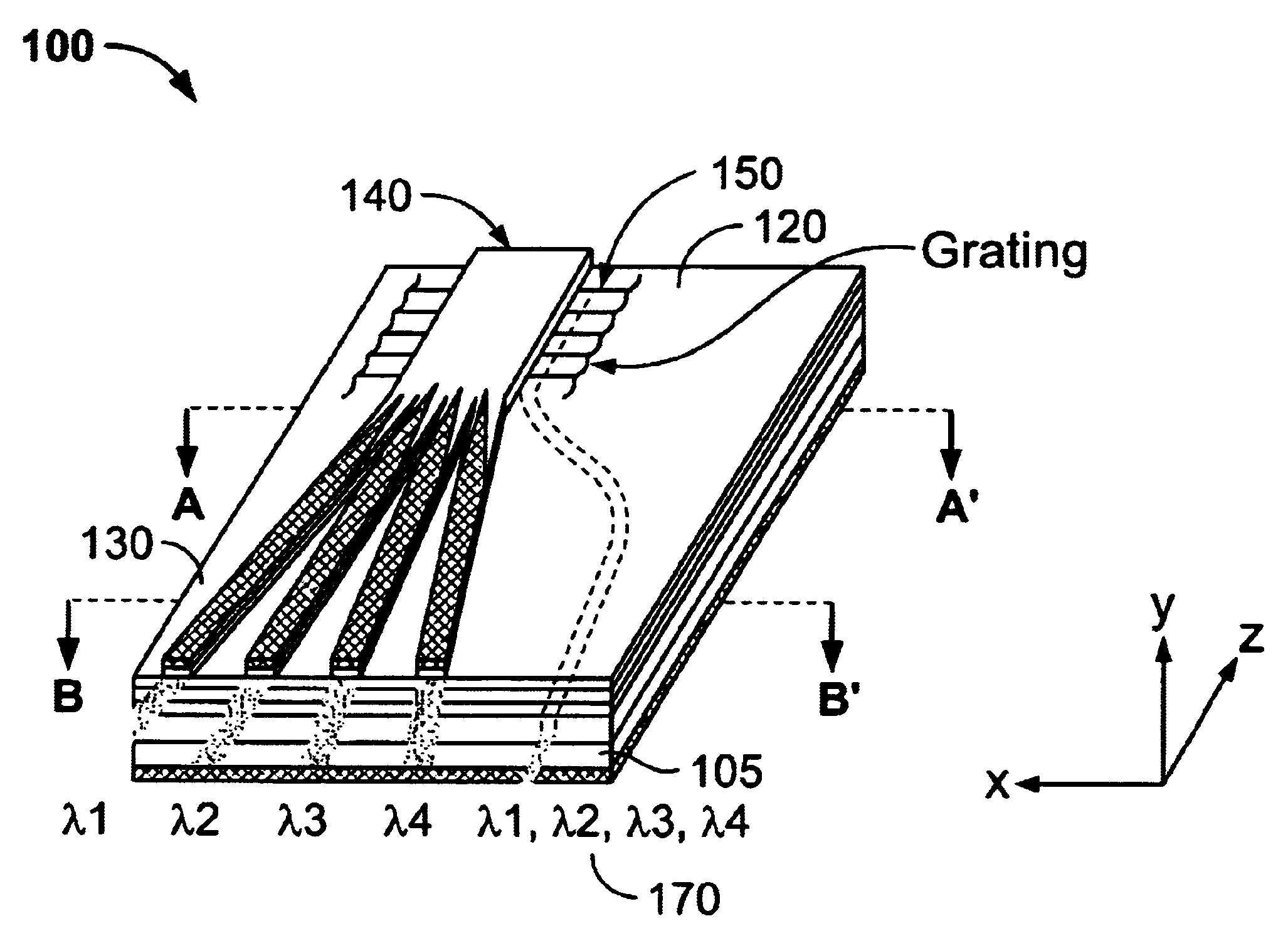
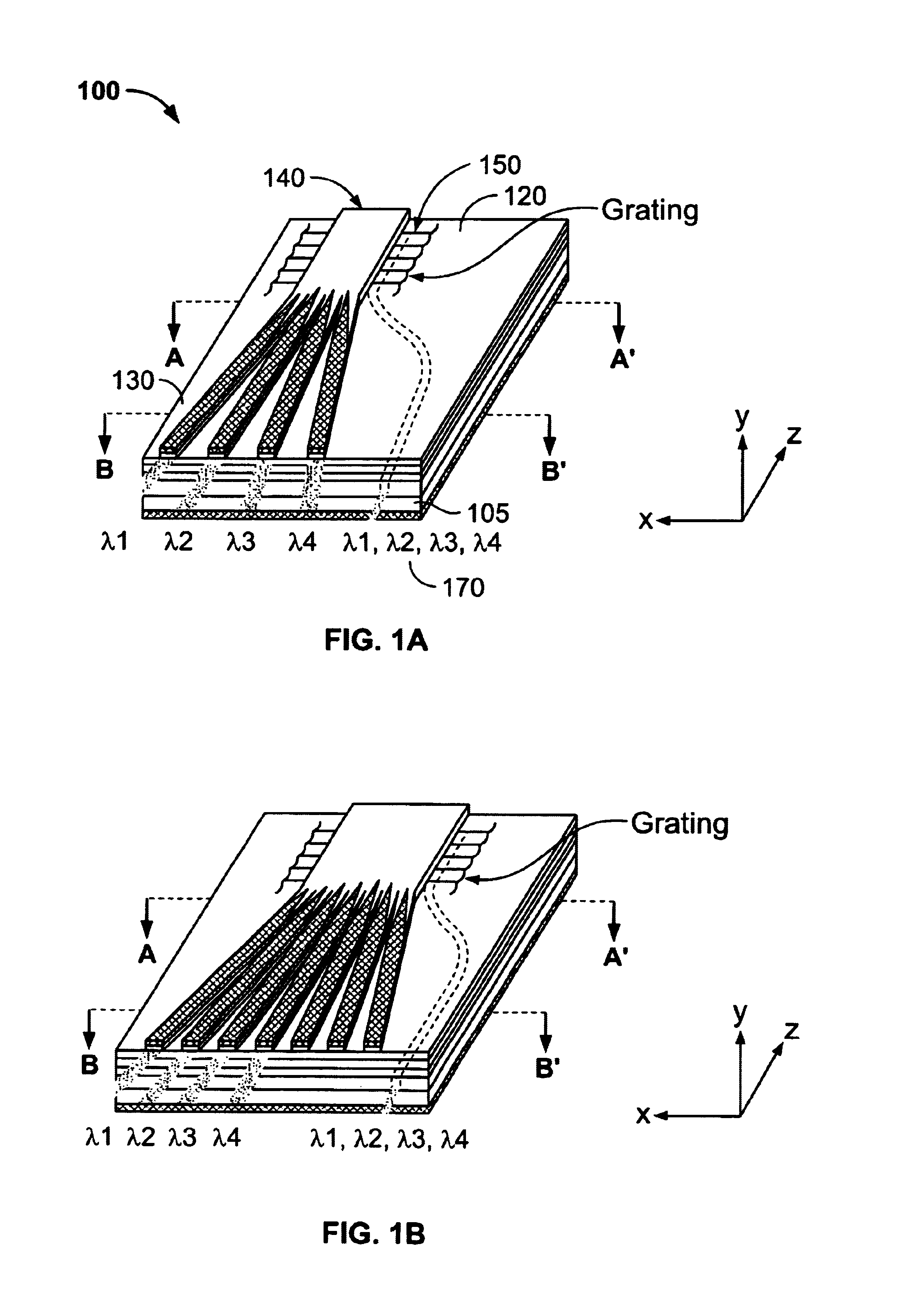
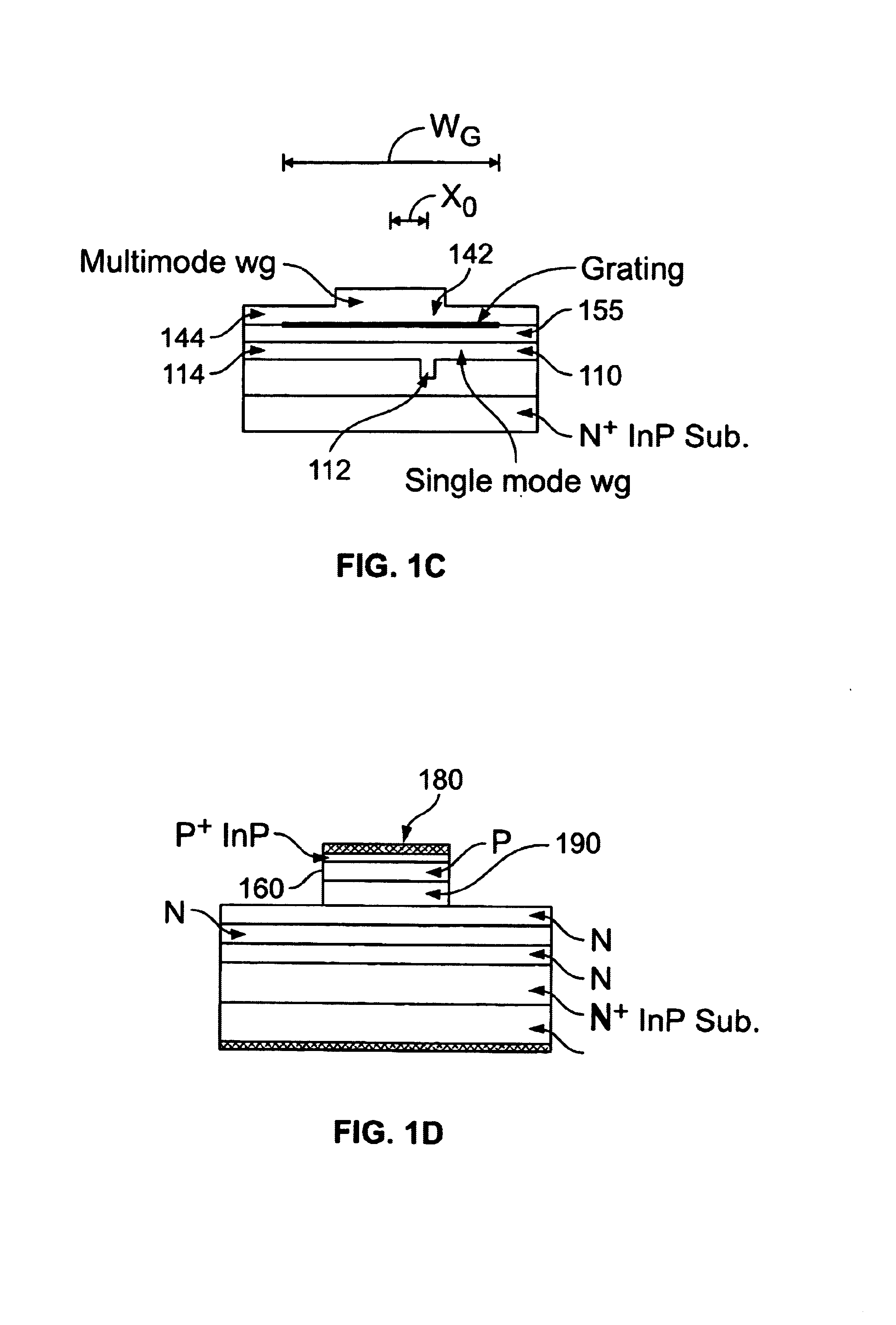
[0032]Referring to FIG. 1a, an exemplary embodiment of the present invention will now be described. FIG. 1a shows a coupler-multiplexer permutation switch (CMPS) 100 which acts both as a demultiplexer and a switch. The CMPS 100 includes a single-mode / multi-mode backward coupler 120, and a digital optical switch 130, both mounted on a common substrate 105. The CMPS 100 may also include other features, such as photodetectors, lasers, optical amplifiers or other features known in the art.

[0033]In a preferred embodiment, a single-mode waveguide (not shown) is coupled with the digital optical switch 130 by using the single-mode / multi-mode backward coupler 120. The central idea of the CMPS 100 is to map a wavelength spectrum 170 of the input wavelength-division-multiplexing (WDM) channels carried in a single-mode waveguide into a modal spectrum of a multi-mode waveguide 140, and then to demultiplex and permutate the wavelength-assigned modes. The mapping is carried out in a single-mode / mu...


PUM


Abstract

A coupler-multiplexer permutation switch (CMPS) integrates multiplexng and switching functions on a single substrate. It has a single-mode/multi-mode backward coupler followed by a digital optical switch (DOS). In the CMPS, the single-mode waveguide channels are phase-matched through a grating with the corresponding, backward-propagating modes of a multi-mode waveguide. The different modes are subsequently separated in a digital optical switch. Different permutations are obtained by electronically controlling an effective-index distribution of DOS output waveguides.

Description

BACKGROUND OF THE INVENTION[0001]1. Field of the Invention[0002]The present invention relates to Wavelength-Division Multiplexing (WDM) networks. In particular, the present invention relates to optical network structures that perform multiplexing and switching of WDM signals.[0003]2. Description of the Related Art[0004]In recent years, communication technology has rapidly and significantly improved. Today, much information is transmitted via optical fibers which allow the transport of information at high data rates. Optical fibers also offer much higher bandwidth than conventional coaxial communications. Nevertheless, an increased data transmission through communication networks places an increasing demand on communications link bandwidth. WDM is an attractive technique for increasing the aggregate capacity of optical networks. In a wavelength division multiplexed optical communication system, several different channels at different optical wavelengths are combined into a fiber to a...

Claims


Application Information

Patent Timeline
Patent Type & Authority Patents(United States)
IPC IPC(8): G02B6/293G02B6/34H04J14/02
CPCB82Y20/00G02B6/12007G02F1/025G02B6/12019G02B2006/12107G02F1/01708G02F2201/307G02F2203/055G02F2203/585
Inventor RAMADAN, TAREK A.
Owner THE TRUSTEES OF COLUMBIA UNIV IN THE CITY OF NEW YORK
Why Eureka
Try Eureka