Power available and limitation indicator for use with an aircraft engine

a technology for aircraft engines and limitation indicators, which is applied in the direction of machines/engines, liquid/fluent solid measurements, instruments, etc., can solve the problems of overly conservative usable power limits, limited power available for turbine engines, and manufacturers usually do not even provide a way to calculate how much power is actually availabl

Inactive Publication Date: 2007-05-01
PRECISION INNOVATIONS
View PDF23 Cites 34 Cited by
  • Summary
  • Abstract
  • Description
  • Claims
  • Application Information

AI Technical Summary

Problems solved by technology

Power limitations for turbine engines are a result of several factors.
Because a turbine engine can compress more air to increase the available air density, power limitations typically depend on the physical factors listed above.
Given the broad range of altitude and temperatures that can be encountered by a piston powered aircraft, the colored arcs often provide false confidence that more power is available than current conditions dictate, or the colored arcs depict overly conservative usable power limits.
Manufacturers usually do not even provide a way to calculate how much power is actually available.
However, safety problems can occur when the actual power available is less than the maximum power limitation because the pilot may be unaware that the aircraft can not produce the maximum power limitation.
However, above the critical altitude the power available will be below the manufacturers limit.
In the case where a pilot attempts to use power in excess of what is actually available, potential safety of flight issues arise.
Exceeding available engine power causes reduced rotor RPM, which if not corrected by immediate pilot action results in “rotor stall” with often catastrophic results.

Method used


Image

  • Power available and limitation indicator for use with an aircraft engine
  • Power available and limitation indicator for use with an aircraft engine
  • Power available and limitation indicator for use with an aircraft engine

Examples


embodiment

A Commercial Embodiment

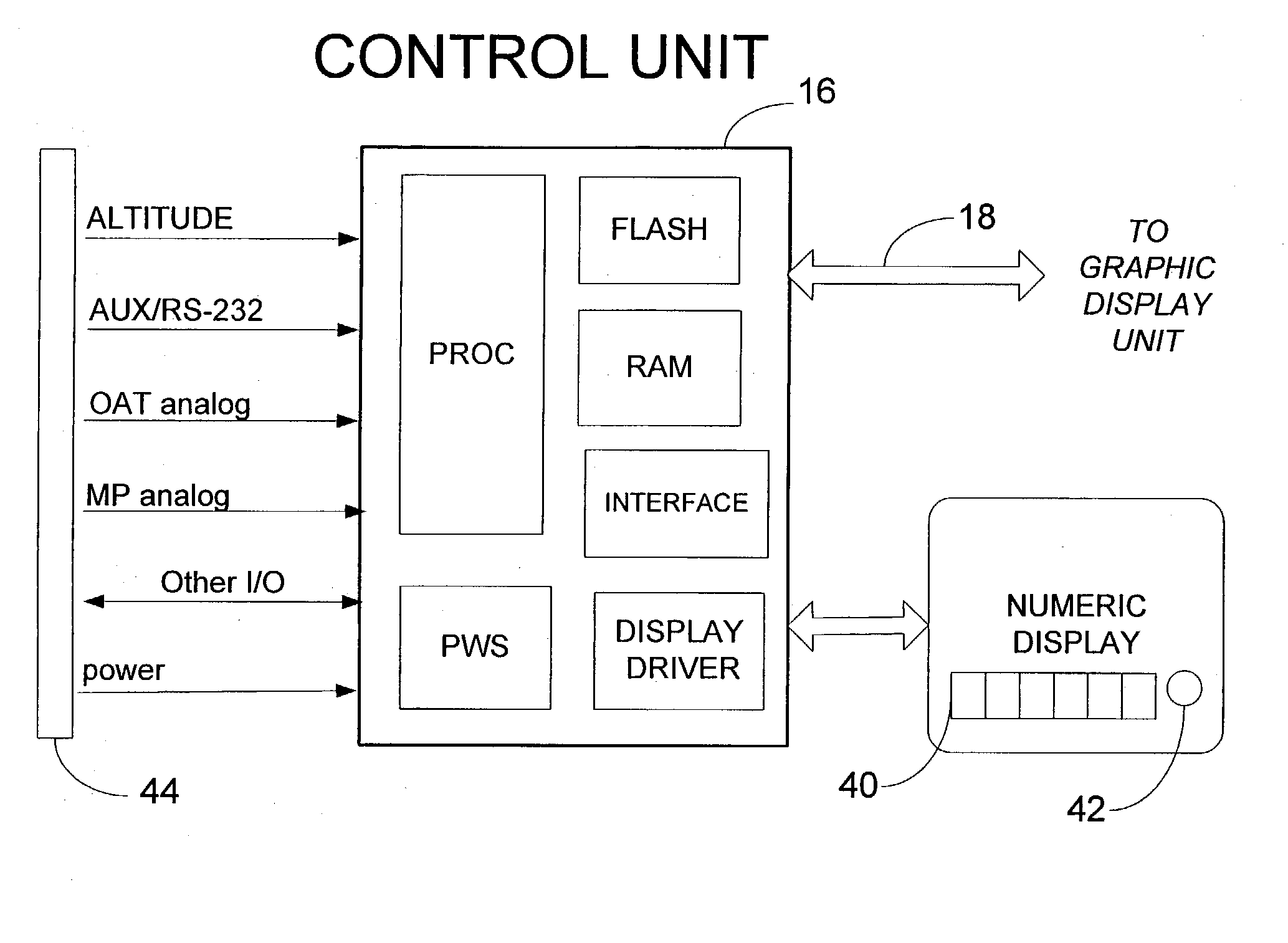
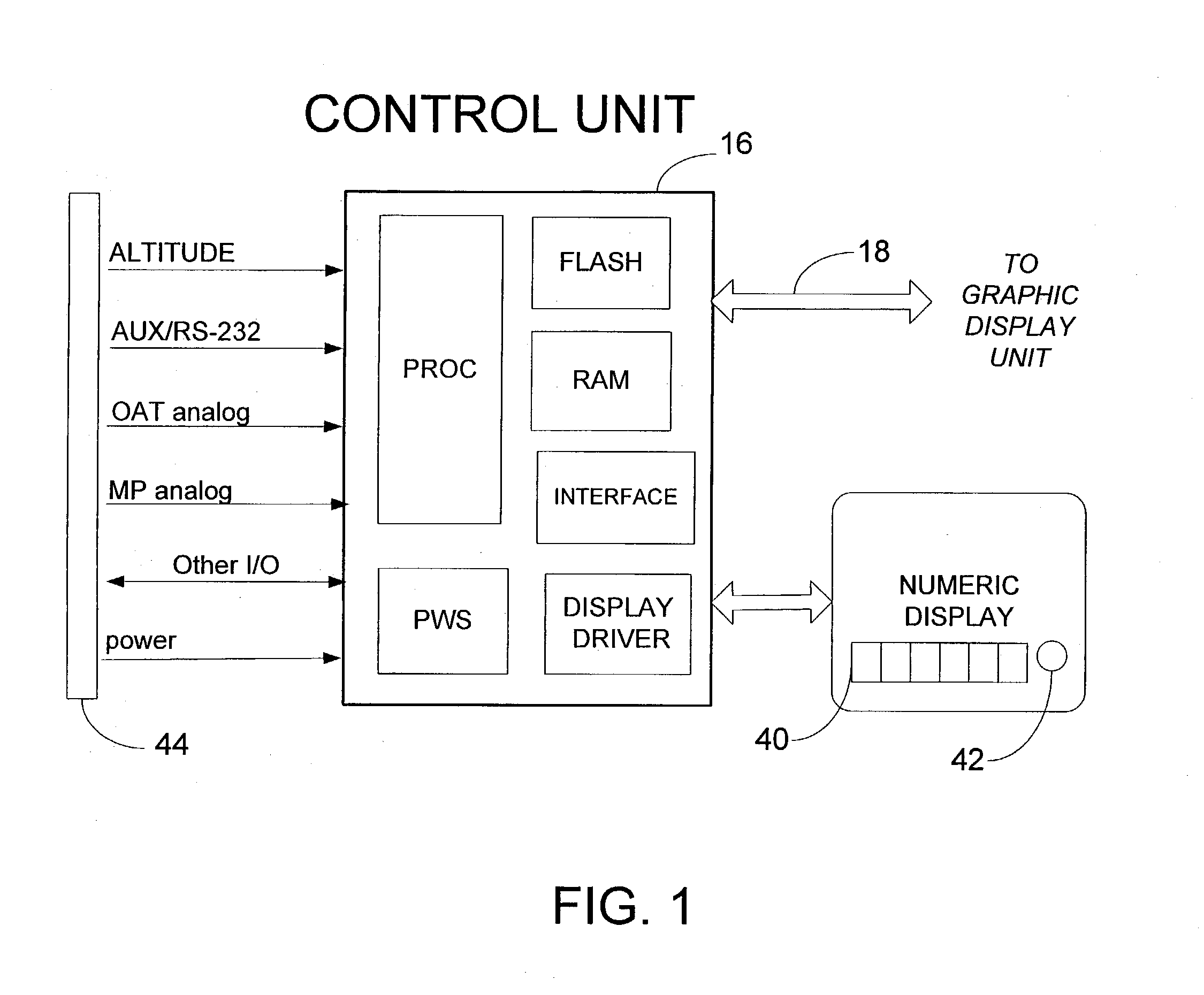
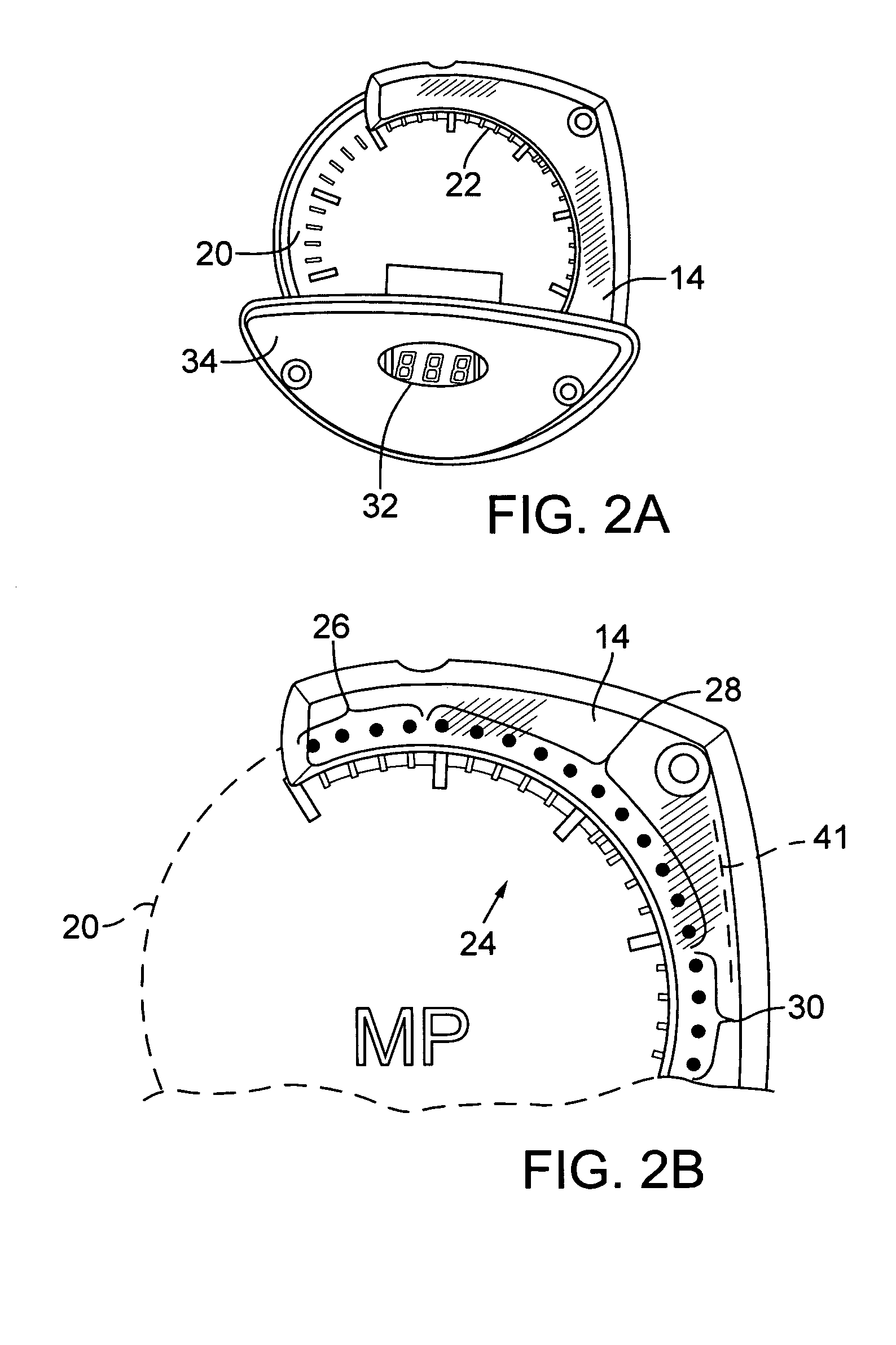
[0060]Several aspects of the invention are further described below in the context of a commercial embodiment called the “PALi” (for “Performance Available and Limitations Indicator”), a helicopter performance calculator and display system developed by the present inventor. It accepts altitude, air temperature, fuel on-board and engine manifold pressure inputs, as explained above, and calculates (in substantially real time) the following: (1) maximum amount of power the engine can produce at these conditions; (2) limitations set by the aircraft manufacturer on power that may be used; (3) maximum airspeed and hover weight allowed under these conditions; (4) percent power used (the “torque gauge”); and (5) amount of power remaining (the “green / yellow power arc”). These values are displayed both graphically (with a color “power arc”) and numerically (on four- and eight-character alphanumeric displays) for the pilot to easily see and interpret.

1. What is PALi?

[0061...


PUM

PropertyMeasurementUnit
pressure altitudeaaaaaaaaaa
density altitudeaaaaaaaaaa

Abstract

An instrument for use in a helicopter includes a performance calculator typically housed in a control unit (16) and a display unit (14). The system receives electronic indicia (44) of current altitude, air temperature, fuel on-board and engine manifold pressure, and calculates (in substantially real time) the following: (a) maximum amount of power the engine can produce at these conditions; (b) limitations set by the aircraft manufacturer on power that may be used; (c) maximum airspeed and hover weight allowed under these conditions; (d) percent power used (the “torque gauge”); and (e) amount of power remaining available. The power display unit has an arcuate series (24) of light elements fitted around the standard MP (20) gauge to provide graphic indicia (26, 28, 30) of power available for the pilot to easily see and interpret.

Description

COPYRIGHT NOTICE[0001]© 2003 Precision Innovations, LLC. A portion of the disclosure of this patent document contains material which is subject to copyright protection. The copyright owner has no objection to the facsimile reproduction by anyone of the patent document or the patent disclosure, as it appears in the Patent and Trademark Office patent file or records, but otherwise reserves all copyright rights whatsoever. 37 CFR § 1.71(d).TECHNICAL FIELD[0002]The present invention relates to determining and displaying the power available for a piston powered aircraft engine.BACKGROUND OF THE INVENTION[0003]Helicopters are normally powered by either a piston driven engine or a turbine engine. Power limitations for turbine engines are a result of several factors. Those factors typically include the following: an internal turbine temperature limit; a rotation per minute (RPM) limit; and a torque limit. Because a turbine engine can compress more air to increase the available air density, ...

Claims


Application Information

Patent Timeline
Patent Type & Authority Patents(United States)
IPC IPC(8): G01D1/00G01L3/24G01L7/00
CPCG01L3/24
Inventor VOLLUM, STEPHEN H.
Owner PRECISION INNOVATIONS
Why Eureka
Try Eureka