
Method of manufacturing a microscale nozzle

a micro-scale nozzle and manufacturing method technology, applied in the direction of electrolysis, chemical vapor deposition coating, metal rolling stand, etc., can solve the problems of not being able to perform all desired evaluation on the chip, wasting a lot of time idle, and expensive mass spectrometer devices

Inactive Publication Date: 2007-05-08
AMIC AB (SE)
View PDF10 Cites 8 Cited by
  • Summary
  • Abstract
  • Description
  • Claims
  • Application Information

AI Technical Summary

Benefits of technology

[0013]As reuse of electrospray systems increases the risk for contamination of the test sample, it is of great interest to produce disposable electrospray systems. Therefore a new method to manufacture microscale nozzles, especially electrospray nozzles, suitable for mass-production is needed.

Problems solved by technology

However, it is not possible to perform all desired evaluation on the chip, and sometimes the sample has to be transferred into an external analytical device.
Mass spectrometers are expensive devices and usually they spend a lot of time idle as the samples which, are to be analysed are often loaded one at a time into the electrospray.
The use of the same nozzle for several samples leads to a risk of cross-contamination and the measures taken to avoid this, such as rinsing between samples, lead to extra costs and decrease the effective working time.
Unfortunately it has been found that these measures are not sufficient as the resulting electrospray is unsatisfactory, and that cross-contamination still may occur.
From an electrospray point of view, this system is the most preferred one, but it is certainly not suitable for mass-production.
As this method involves several steps of high precision patterning and as it is a silicon-based process, it requires advanced production means, which leads to a relatively expensive process.

Method used


Image

  • Method of manufacturing a microscale nozzle
  • Method of manufacturing a microscale nozzle
  • Method of manufacturing a microscale nozzle

Examples


example

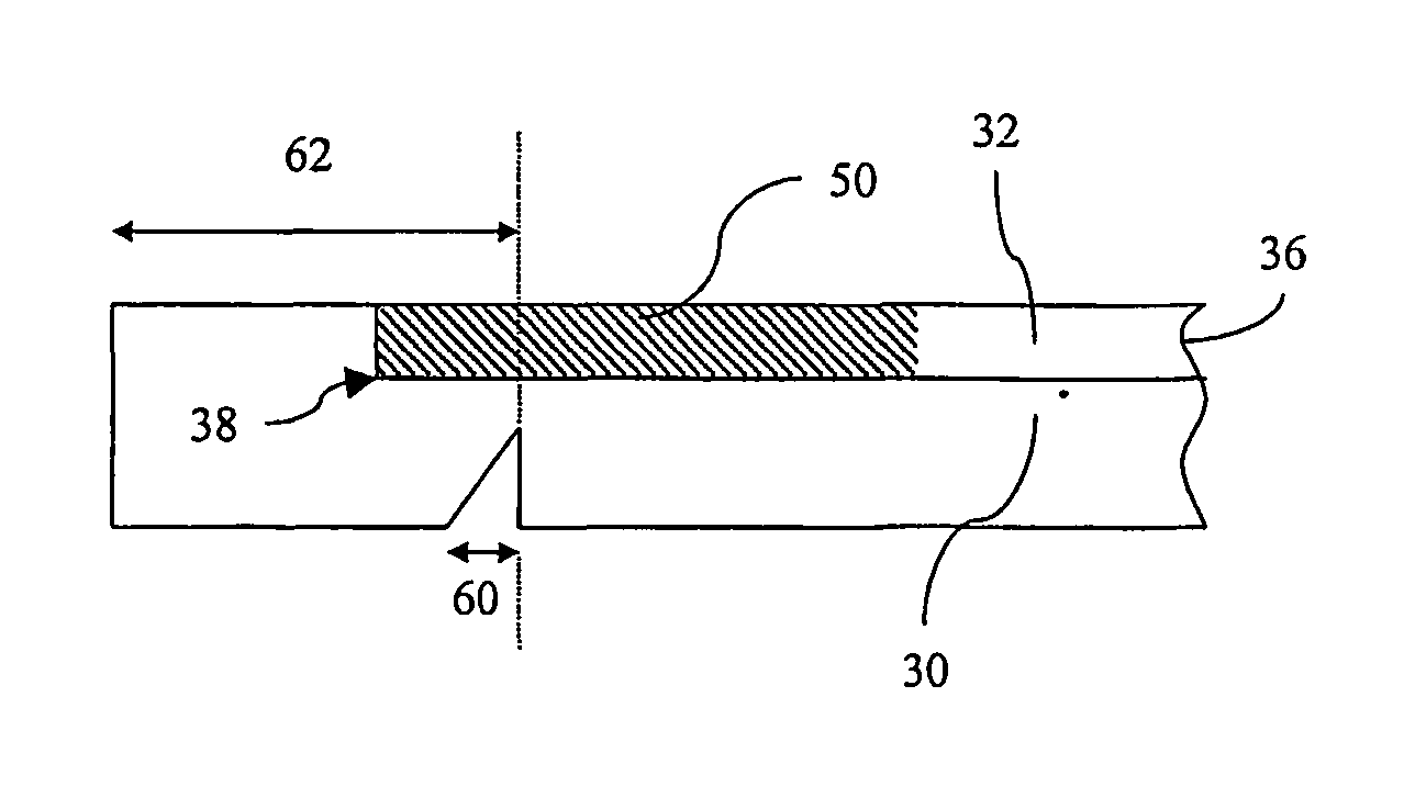
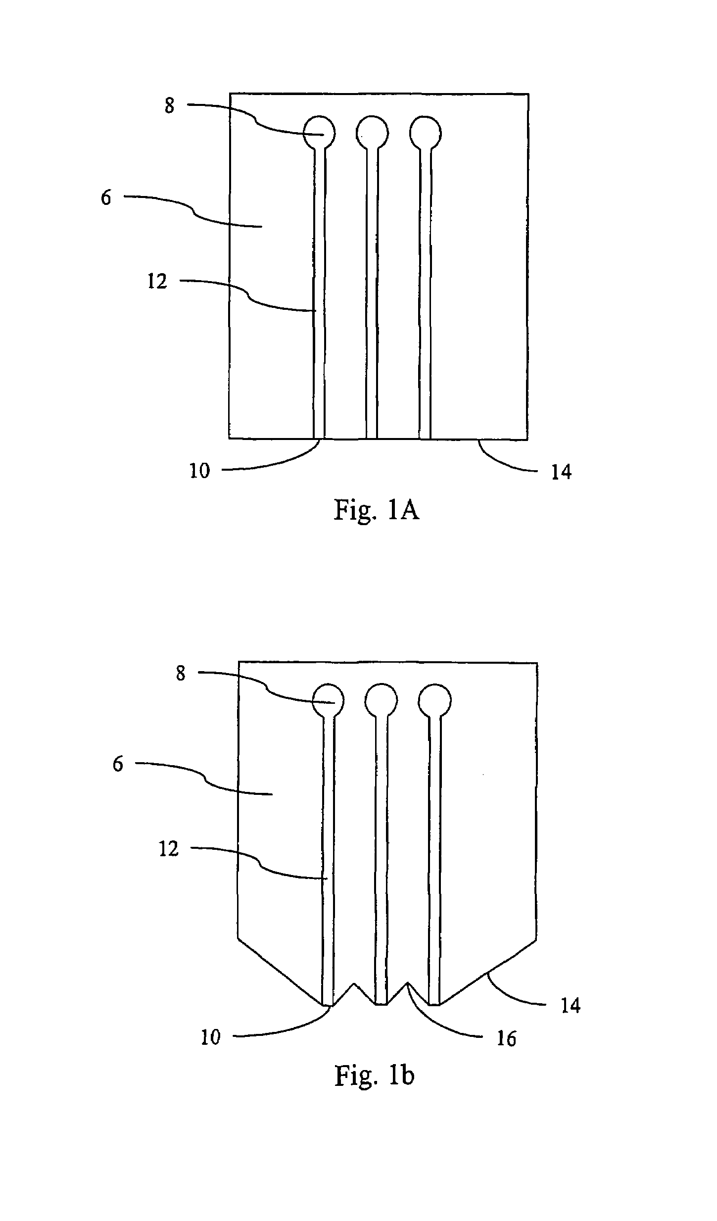
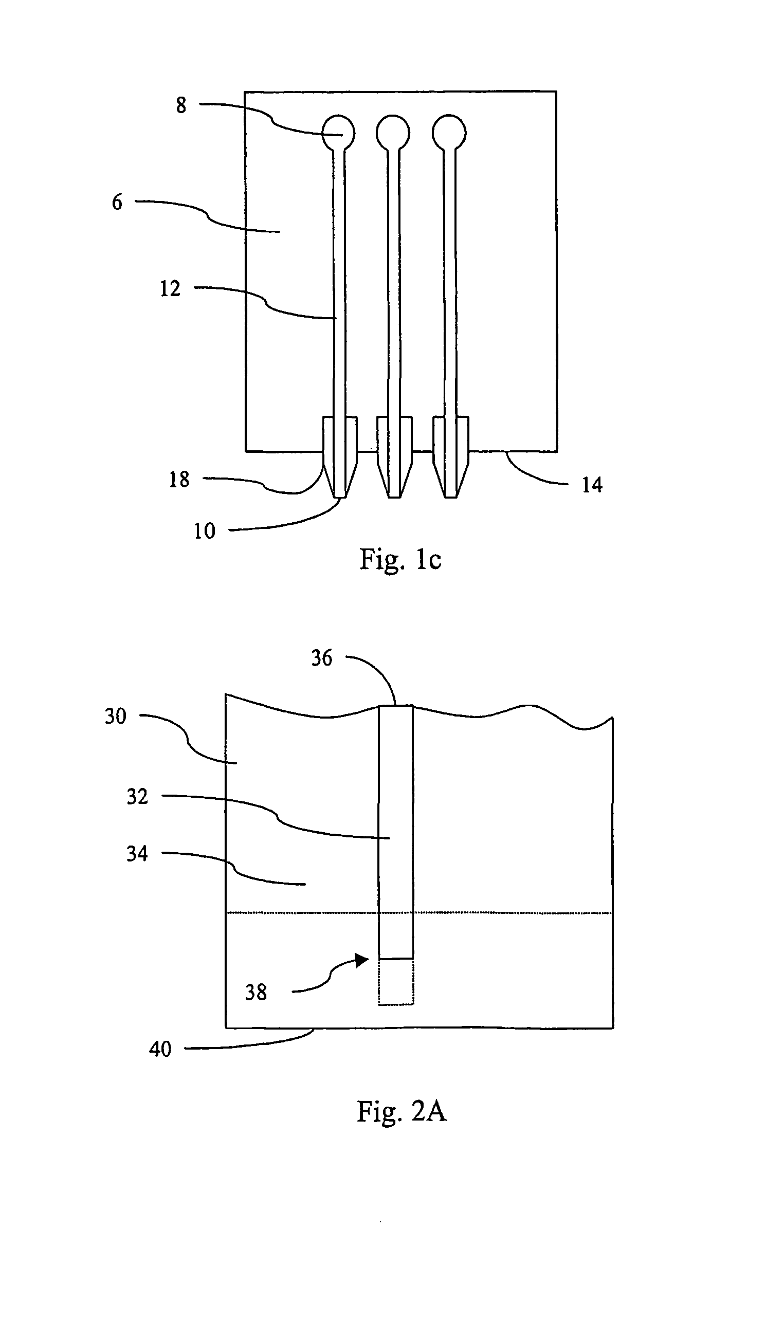
[0033]This example describes one possible way to produce a microchip fluidic system with a polymeric substrate and a metallic nozzle, which process is especially suitable for massproduction.[0034]1. Injection-molding of a polycarbonate-substrate 30 having a microscale channel 32 in the top surface 34 and a notch 60 in the bottom surface.[0035]2. Depositing, on the top surface34 of the substrate 30, a thin metal layer over the nozzle-forming section of the microscale channel 32, using a shade-mask. The deposited metal layer will act as a seed-layer in the electroplating-step described below.[0036]3. Deposition of a positive photoresist-layer to form a thin resist on the top surface 34 of the substrate 30, and a thick resist is made to cover and fill the microchannel 32 using a doctor-blade applying technique. After the deposition, the substrate 30 is soft baked.[0037]4. Exposing the substrate 30 without a mask, such that the thin resist on the top surface 34 of the substrate 30 will ...


PUM

PropertyMeasurementUnit
depthaaaaaaaaaa
conductingaaaaaaaaaa
distanceaaaaaaaaaa

Abstract

Method of manufacturing a microscale nozzle, comprising the steps of forming a microscale channel in the top surface of a substrate, said microscale channel comprising an inlet end and a nozzle-end, depositing a nozzle-forming layer in a section of the microscale channel, and removing material from the substrate at the nozzle-end of the microscale channel to expose at least a portion of said nozzle-forming layer. The manufactured microscale nozzle may be used for transferring a liquid sample form a microchip fluidic system into an external analytical device.

Description

[0001]This application is the national phase under 35 U.S.C. § 371 of PCT International Application No. PCT / SE01 / 02753 which has an International filing date of Dec. 12, 2001, which designated the United States of America.[0002]1. Field of the Invention[0003]The present invention relates to microscale fluidic devices and methods for their manufacture. More specifically, the invention relates to a new microscale nozzle and a method of manufacturing the same.[0004]2. Prior Art[0005]Extensive efforts are currently taking place to reduce the volumes of reagents and samples used in assays and new devices which are capable of performing assays on volumes of the order of nanolitres and picolitres are under development. However, it is not possible to perform all desired evaluation on the chip, and sometimes the sample has to be transferred into an external analytical device. This transfer may be done in several different ways, such as by an outlet-port on the chip which is directly connecte...

Claims


Application Information

Patent Timeline
Patent Type & Authority Patents(United States)
IPC IPC(8): B21D53/76G01N30/72B41J2/16B81B1/00B81C1/00
CPCB41J2/162B41J2/1626B41J2/1631B41J2/1637B41J2/1643B41J2/1642Y10T29/49002Y10T29/49155Y10T29/4998Y10T29/49401
Inventor OHMAN, PER OVEANDERSSON, PER
Owner AMIC AB (SE)
Learn More