
Phase modulation apparatus, polar modulation transmission apparatus, wireless transmission apparatus and wireless communication apparatus

a polar modulation and transmission apparatus technology, applied in the direction of angular modulation details, pulse automatic control, electrical apparatus, etc., can solve the problems of increased power consumption, difficult to obtain desired output signals (i.e. rf modulation signals), and widening the pll bandwidth. , to achieve the effect of excellent rf phase modulation signals and high quality

Inactive Publication Date: 2007-05-08
PANASONIC CORP
View PDF4 Cites 27 Cited by
  • Summary
  • Abstract
  • Description
  • Claims
  • Application Information

AI Technical Summary

Benefits of technology

"The present invention provides a phase modulation apparatus and a polar modulation transmission apparatus that can achieve high-quality transmission signals even when the modulation sensitivity of a voltage controlled oscillator varies. The phase modulation apparatus includes a PLL circuit, a frequency divider, an adder, a phase detector, a comparator, and a gain controller. The polar modulation transmission apparatus includes an amplitude phase converter, a PLL circuit, a frequency divider, an adder, a high frequency power amplifier, a coupler, a phase detector, a comparator, and a gain controller. The wireless transmission apparatus includes a transmitter and a receiver. The wireless communication apparatus includes a transmitter and a receiver."

Problems solved by technology

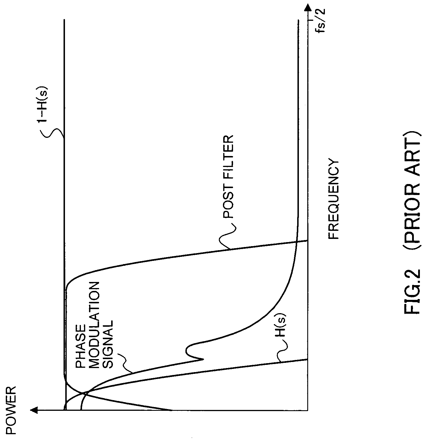
However, widening the PLL bandwidth has the risk of deteriorating noise characteristics.
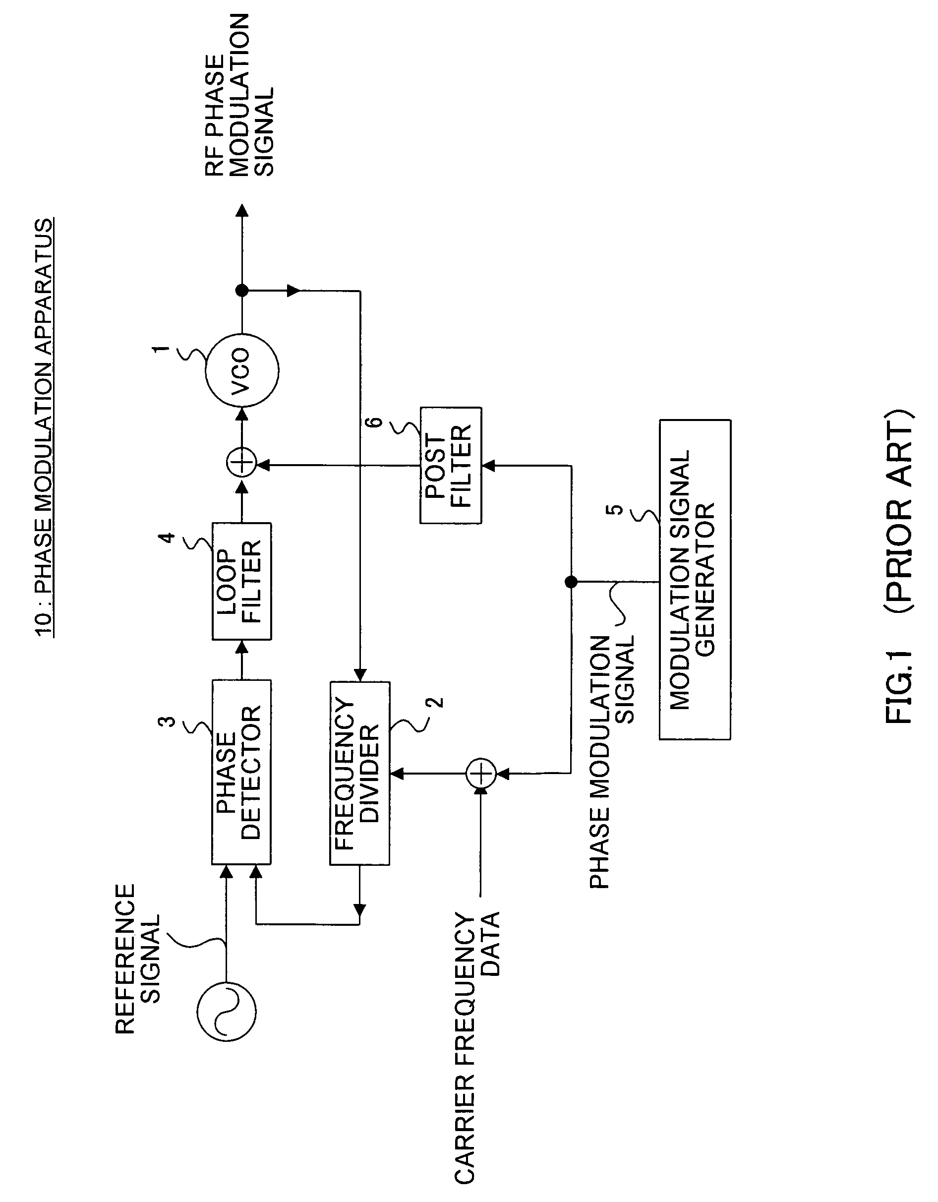
When the modulation sensitivity of VCO 1 varies, this makes it difficult to obtain desired output signals (i.e. RF modulation signals).
However, increasing the resolution requires high speed clock, which gives a rise to another problem of increased power consumption.
In addition, the tradeoff with power consumption and the maximum operation frequency of the circuit set further limitations to increasing the clock, and so, in reality, the DDS output frequency cannot be heightened much.
As a result, the PLL bandwidth needs to be made narrow, which gives a rise to yet another problem of increased PLL lock up time.

Method used


Image

  • Phase modulation apparatus, polar modulation transmission apparatus, wireless transmission apparatus and wireless communication apparatus
  • Phase modulation apparatus, polar modulation transmission apparatus, wireless transmission apparatus and wireless communication apparatus
  • Phase modulation apparatus, polar modulation transmission apparatus, wireless transmission apparatus and wireless communication apparatus

Examples


embodiment 1

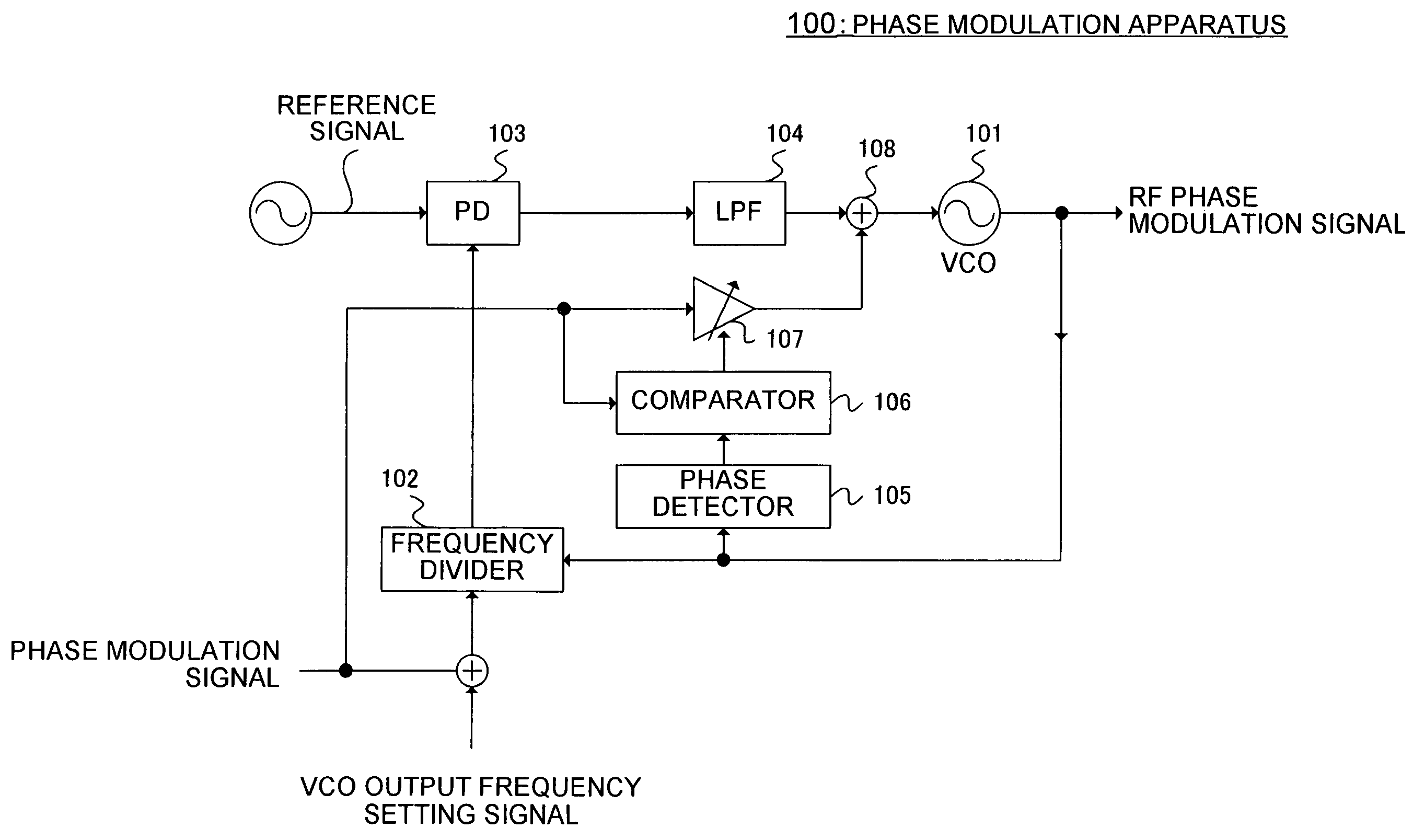
[0043]FIG. 6 illustrates the configuration of a phase modulation apparatus according to Embodiment 1 of the present invention. Phase modulation apparatus 100 has: voltage controlled oscillator (VCO) 101 that changes the oscillation frequency in accordance with the voltage in the control voltage terminal; frequency divider 102 that divides the frequency of an RF phase modulation signal outputted from VCO 1; phase detector (PD) 103 that compares the phase of the output signal of frequency divider 102 with the phase of a reference signal and outputs a signal in accordance with the phase difference between the two signals; and loop filter (LPF: Low Pass Filter) 104 that equalizes the output signal of phase detector 103 and outputs the result. Phase modulation apparatus 100 thus adds a baseband input phase modulation signal to a VCO output frequency setting signal (i.e. carrier frequency data) and provides the result to frequency divider 102 as the frequency division ratio, thereby perfo...

embodiment 2

[0055]FIG. 7 illustrates the phase modulation apparatus of the present embodiment. Parts in FIG. 7 that are identical to ones in FIG. 6 will be assigned the same reference numerals as in FIG. 6. In comparison to phase modulation apparatus 100 of Embodiment 1, phase modulation apparatus 200 has down converter 201 that down converts an RF phase modulation signal and sends the result to phase detector 105.

[0056]As shown in FIG. 7, down converter 201 has, for example, mixer 202, synthesizer 203, and low pass filter (LPF) 204, forming a configuration in which mixer 202 receives as input an RF phase modulation signal and a frequency generated by synthesizer 203 and mixer 202 lowers the frequency of the RF phase modulation signal to the frequency generated by synthesizer 203. The configuration of the down converter is by no means limited to the one described above, and any circuits would be applicable as long as the frequency of the RF phase modulation signal can be lowered.

[0057]The signa...

embodiment 3

[0059]FIG. 8 illustrates the phase modulation apparatus of the present embodiment. Parts in FIG. 8 that are identical to ones in FIG. 6 will be assigned the same reference numerals as in FIG. 6. In comparison to phase modulation apparatus 100 of Embodiment 1, phase modulation apparatus 300 has: frequency divider 301 that divides the frequency of an RF phase modulation signal outputted from VCO 101 and supplies the result to frequency divider 301; and bandwidth conversion circuit 302 that converts bandwidth of a phase modulation signal in accordance with the frequency division ratio of frequency divider 301 and supplies to result to comparator 106.

[0060]By thus providing frequency divider 301 and lowering the frequency of the RF phase modulation signal inputted in phase detector 105, it is possible to simplify the configuration of phase detector 105 and improve the accuracy of detection.

[0061]By the way, the bandwidth of the RF phase modulation signal decreases to 1 / D after the RF ph...


PUM


Abstract

A phase modulation apparatus is provided whereby excellent RF phase modulation signals can be obtained even when the modulation sensitivity of a voltage controlled oscillator varies. Phase modulation apparatus 100 has: phase detector 105 that performs phase detection with respect to an RF phase modulation signal outputted from VCO 101; comparator 106 that compares the phase of the detected signal with the phase of a baseband phase modulation signal and outputs the difference between the signals; variable gain amplifier 107 that controls the gain of the baseband phase modulation signal based on the output of comparator 106 and supplies the gain-controlled baseband phase modulation signal to VCO 101. By this means, the signal level of the baseband phase modulation signal that is supplied to VCO 101 can be controlled in accordance with the modulation sensitivity of VCO 101, so that phase modulation apparatus 100 can be realized whereby excellent RF phase modulation signals even when the modulation sensitivity of VCO 101 varies.

Description

BACKGROUND OF THE INVENTION[0001]1. Technical Field[0002]The present invention relates specifically to a phase modulation apparatus, polar modulation transmission apparatus, wireless transmission apparatus and wireless communication apparatus that perform phase modulation utilizing the PLL (Phase Locked Loop).[0003]2. Description of the Related Art[0004]Heretofore, phase modulation apparatuses utilizing the PLL have been widely used to modulate carrier signals by baseband modulation signals and form transmission signals (that is, to up-convert baseband modulation signals to radio frequency). Generally, phase modulation apparatuses of this type are expected to realize low costs, low power consumption, excellent noise characteristics, and high modulation accuracy. To modulate signals using the PLL, and, in particular, to improve modulation accuracy using the PLL, the PLL frequency bandwidth (i.e. PLL bandwidth) is preferably wider than the frequency bandwidth of the modulation signal ...

Claims


Application Information

Patent Timeline
Patent Type & Authority Patents(United States)
IPC IPC(8): H03C3/06H03C3/09H03L7/00
CPCH03C3/0925H03C3/0933H03C3/0941H03C3/095H03C3/0983
Inventor HIRANO, SHUNSUKEADACHI, HISASHI
Owner PANASONIC CORP
Learn More