Pseudo-BJT based retinal focal-plane sensing system

a focal-plane sensing and focal-plane technology, applied in the field of optical sensing systems, can solve the problems of reducing the current gain of pbjts, the chip area of silicon retina of resistor networks is still too large, and the ability to enable retina and cerebrum visual functions to be performed by silicon chips, so as to achieve contrast enhancement and effectively reduce the size of imaging data

Active Publication Date: 2007-05-08
ALFA PLUS SEMICON
View PDF9 Cites 10 Cited by
  • Summary
  • Abstract
  • Description
  • Claims
  • Application Information

AI Technical Summary

Benefits of technology

[0008]Firstly, the invention is applicable to optical sensors, such as bar-code / character readers, by employing the design of the silicon retinal circuit structure. The high dynamic range characteristics of utilizing the silicon retinal circuit structure enables an optical sensor to be operated under less-lighting environment without applying additional illuminant. In addition, a silicon retinal circuit has the contrast enhancement characteristic that inputted gray-scale images can be enhanced and outputted as black / white images, thereby effectively reducing imaging data size and enabling the optical sensor to be suitable for the application of instant image processing. Therefore, the optical sensor is suitable for bar-code / character readers.

Problems solved by technology

How to enable retina and cerebrum visual functions to be performed by silicon chip has become a great challenge in recent years.
The Resistor Network in this structure is only composed of megaohms resistance; however, a large resistance still occupies a larger chip area during the Integrated Circuit(IC) design.
Even though there have been various researches and methods for improving the drawback mentioned above, nevertheless, the chip area of silicon retina of Resistor Network is still too large.
In addition to the above drawbacks of Resistor Network, there are two problems while PBJTs are applied: (1) the chip area is large when BJT-based retinal sensor is manufactured; (2) the PBJTs have smaller current gain when the technology scales down to 0.25 um or below.
In view of the drawbacks and problems mentioned above, it is obvious that BJT-based technique is not suitable to be applied in the future manufacturing and optical applications.

Method used


Image

  • Pseudo-BJT based retinal focal-plane sensing system
  • Pseudo-BJT based retinal focal-plane sensing system
  • Pseudo-BJT based retinal focal-plane sensing system

Examples


Embodiment Construction

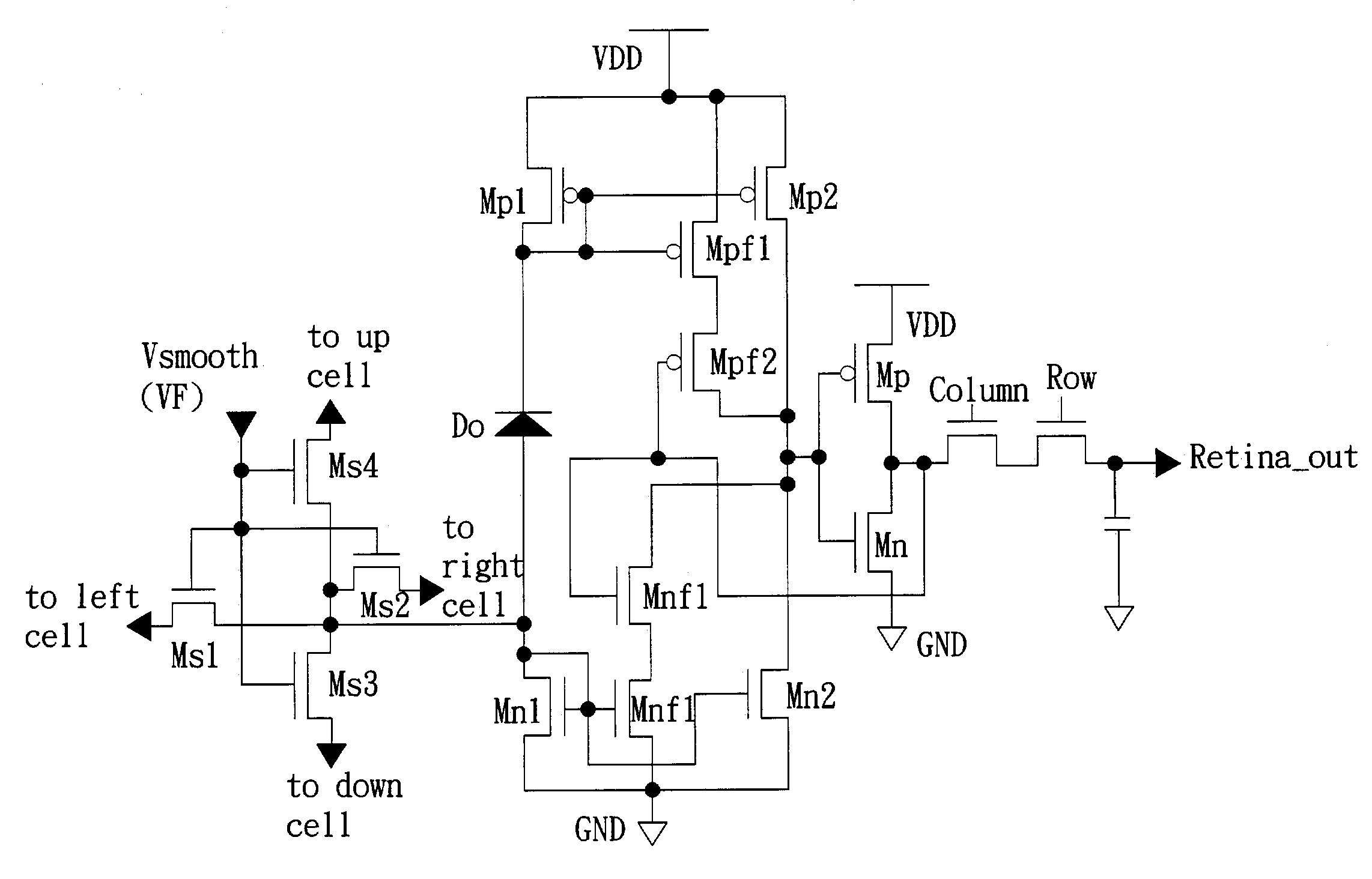
[0026]This invention proposes a Pseudo-BJT based retinal focal-plane sensing system, which is a system with instant image sensing and front-end processing having the advantageous features of high dynamic range and instant image processing, etc. The invention is suitable to be applied in optical sensors, such as bar-code / character readers. This invention has the following features: Firstly, Adaptive current Schmitt trigger of the invention can be adjusted adaptively according to the value of induced photocurrent, which enhances noise immunity and eliminate noise disturbance. The proposed Pseudo-BJT focal-plane sensor circuit is operated in the subthreshold region. Therefore, the total power consumption of this invention is far less than that of BJT-based retinal sensor circuit. The noise disturbance sometimes misled the retinal sensor, that is, the sensor mistakes an unreality for a detected object owing to the impact of noise disturbance, thereby an adaptive current Schmitt trigger ...


PUM


Abstract

A Pseudo Bipolar Junction Transistor(Pseudo-BJT) based retinal focal-plane sensing system is an instant image sensing and front-end processing system with the advantages of high dynamic range and instant image processing. In addition, the system proposes a Pseudo-BJT based retinal focal-plane sensor with adaptive current Schmitt trigger and smoothing network for applying a new Pseudo-BJT circuit structure to mimic parts of functions of the cells in the outer plexiform layer of the real retina. It is suitable to resolve the existing technical drawbacks performing major functions in optical image detecting circuits, such as image recognition, image tracing, robot vision, bar-code / character readers, etc.

Description

BACKGROUND OF THE INVENTION[0001]1) Field of the Invention[0002]The invention relates to an optical sensing system, in particular, a retinal focal-plane sensor chip that is structured on Pseudo Bipolar Junction Transistor (Pseudo-BJT) and comprises a system with an adaptive current Schmitt trigger and a smoothing network for optical image detecting circuits, such as image identification, image tracing, robot vision readers of image, barcode or character, etc.[0003]2) Description of the Prior Art[0004]Rapid development of science and technology has made the semi-conductor and IT industries continuously rising and flourishing, resulting in outstanding changes in considerable application fields. Such changes not only make achievement of science and technology, but also improve our quality of life and alter our patterns of life. Since 1980, the researches in silicon retina have been developed one after another emphasizing how to attain the H cell function by circuits applying Gaussian s...

Claims


Application Information

Patent Timeline
Patent Type & Authority Patents(United States)
IPC IPC(8): H04N3/14G01R19/00H01L27/00H01L31/062H04N5/217H04N5/228H04N5/357H04N5/374H04N5/376H04N5/378
CPCH04N5/23241H04N5/357H04N5/3745H04N5/376H04N25/60H04N25/74H04N25/77
Inventor CHIANG, CHENG-TAWU, CHUNG-YU
Owner ALFA PLUS SEMICON
Why Eureka
Try Eureka