
Method and apparatus for keyboard control with programmable debounce and jog

a keyboard control and programmable debounce technology, applied in the field of methods and apparatus for electronic data entry, can solve the problems of increasing the load on the controller, variable rise, and requiring different debounce periods

Active Publication Date: 2007-05-15
UTC FIRE & SECURITY AMERICAS CORPORATION INC
View PDF6 Cites 22 Cited by
  • Summary
  • Abstract
  • Description
  • Claims
  • Application Information

AI Technical Summary

Benefits of technology

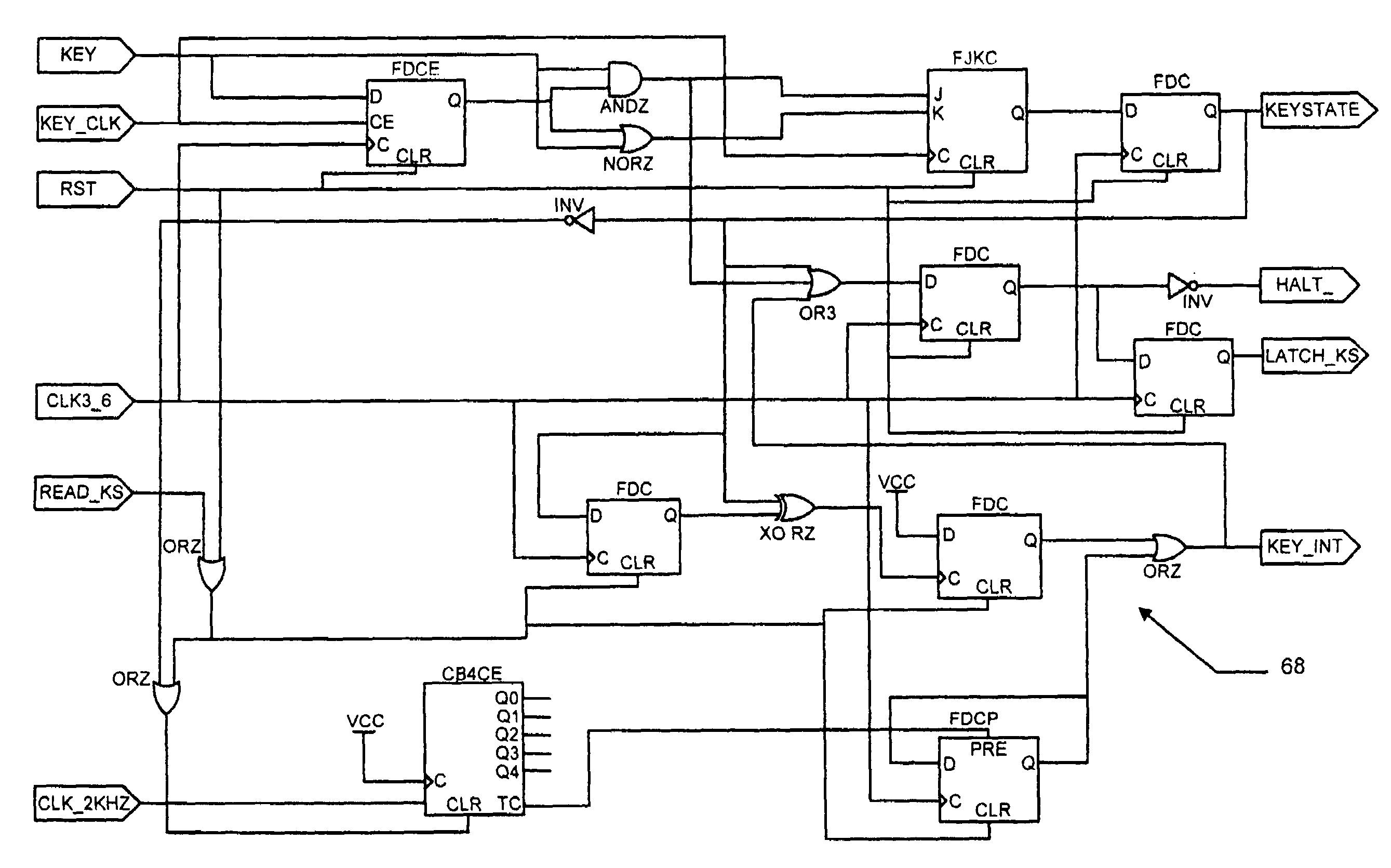
"The present invention provides a method and apparatus for controlling a keyboard that can be used with different manufactures of matrix keyboards and touch screens. The method and apparatus include a programmable register that stores a value indicative of a debounce time for the keyboard and a value indicative of a jog time for a key of the keyboard. The apparatus scans the keyboard for a pressed key and debounces a signal indicative of the pressed key. The apparatus provides electronic signals for key status and jog and asserts an interrupt in accordance with the indicated debounce period and the indicated jog period while the deboned signal indicates that the pressed key is down. The apparatus also prevents keys of the keyboard other than the pressed key from being scanned until the deboned signal indicates that the pressed key has come up. The technical effects of the present invention include improved performance of an operator interface and prevention of spurious operation of an industrial apparatus controlled by a keyboard."

Problems solved by technology

This variable impedance results in variable rise and fall times of make and break signals, thus requiring different debounce periods.
This polling increases the load on the controller and tends to make it less responsive.
The erroneously activated keys may cause unintended and / or unpredictable consequences in the operation of an industrial device.

Method used


Image

  • Method and apparatus for keyboard control with programmable debounce and jog
  • Method and apparatus for keyboard control with programmable debounce and jog
  • Method and apparatus for keyboard control with programmable debounce and jog

Examples


Embodiment Construction

[0016]Configurations described herein include certain signals described as being “active low” or “active high.” Although a choice has to be made for each configuration as to whether these signals are considered “active low” or “active high,” that selection is a design choice that can be left to a technician having ordinary skill in the art of digital circuit design. Once the inventive concepts and configurations described herein are understood, the circuit modifications necessary to effectuate the selection of a signal as being “active low” or “active high” can be made by such a technician.

[0017]The term “keyboard” is used in the most generic sense herein and includes within its scope any type of switch matrix (of any size) for data entry by fingertip operation, including a “keypad” and a “touch screen.” Unless explicitly stated, the terms “keypad” and “keyboard” are used synonymously and interchangeably herein.

[0018]The term “matrix keyboard” as used herein also includes within its...


PUM


Abstract

A method for providing debounce and jog control for a keyboard includes loading a first electronic storage register with a value indicative of a debounce period for the keyboard and loading a second electronic storage register with a value indicative of a jog period for the keyboard. The keyboard is scanned for a pressed key, and a signal indicative of the pressed key is debounced. The method further includes providing electronic signals for key status and jog and asserting an interrupt in accordance with the indicated debounce period and the indicated jog period while the debounced signal indicates the pressed key is down. Keys of the keyboard other than the pressed key are prevented from being scanned until the debounced signal indicates that the pressed key has come up.

Description

BACKGROUND OF THE INVENTION[0001]This invention relates generally to methods and apparatus for electronic data entry and more particularly to methods and apparatus for matrix or touch-screen keyboard control.[0002]In at least one known configuration of an industrial controller or computer, a matrix keyboard or matrix touch screen is scanned continuously to determine whether a key has been pressed. This scanning can be done either via software or hardware polling. Whichever type of polling is used, this configuration requires that a debounce period be determined and a debounce algorithm be developed to prevent data from the keyboard from being contaminated with unintended multiple signaling of each keypress. For matrix keyboards and matrix touch screens from different manufacturers, circuit impedance varies. This variable impedance results in variable rise and fall times of make and break signals, thus requiring different debounce periods.[0003]Some industrial applications require su...

Claims


Application Information

Patent Timeline
Patent Type & Authority Patents(United States)
IPC IPC(8): H03M11/00H03K17/94
CPCH03K5/1254H03M11/20
Inventor LALIBERTE, EDWARD ROBERTSHELTON, WILLIAM TODD
Owner UTC FIRE & SECURITY AMERICAS CORPORATION INC
Learn More