Disk apparatus, data recording method, and data reproduction method for continuous data processing

Inactive Publication Date: 2007-05-15
KK TOSHIBA
View PDF6 Cites 6 Cited by
  • Summary
  • Abstract
  • Description
  • Claims
  • Application Information

AI Technical Summary

Benefits of technology

[0008]A disk apparatus according to one aspect of the present invention comprises an irradiation unit configured to irradiate a recording surface of a disk with a light beam, a reflected light detection unit configured to detect reflected light of the light beam irradiated by the irradiation unit, a focus control unit configured to control focus on the basis of a focus control signal generated from the reflected light detected by the reflected light detection unit, a tilt amount detection unit configured to specify a plurality of regions with different radial positions on the disk, and to detect tilt amounts of respective regions with respect to an optical axis of the light beam irradiated by the irradiation unit on the basis of the focus control signal, a tilt correction unit configured to calculate tilt correction values for respective regions in accordance with the tilt amounts of the respective regions detected by the tilt amount detection unit, and correct a tilt of the optical axis with respect to a predetermined region on the basis of the tilt correction value corresponding to the predetermined region, and a recording unit configured to record data on the predetermined region while the tilt of the optical axis with respect to the predetermined region is corrected by the tilt correction unit.
[0009]A data recording method according to one aspect of the present invention comprises: specifying a plurality of regions with different radial

Problems solved by technology

The influences of disk tilts on recording/reproduction become more serious with increasing density of an optical disk.
Such disk tilt is not uniform over the entire surface of the disk.
Since such continuous recor

Method used


Image

  • Disk apparatus, data recording method, and data reproduction method for continuous data processing
  • Disk apparatus, data recording method, and data reproduction method for continuous data processing
  • Disk apparatus, data recording method, and data reproduction method for continuous data processing

Examples


Embodiment Construction

[0017]A preferred embodiment of the present invention will be described hereinafter with reference to the accompanying drawings.

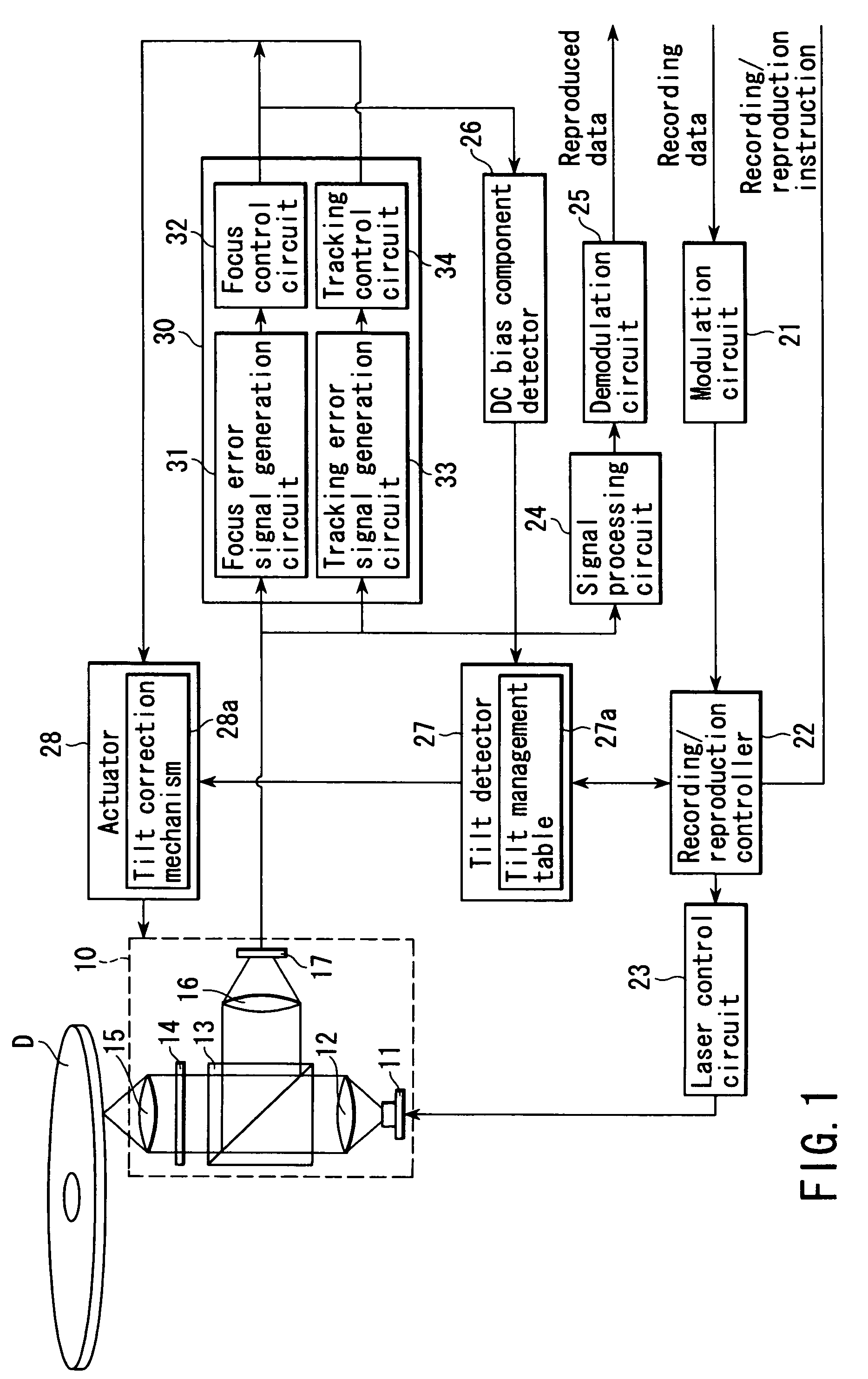
[0018]FIG. 1 is a schematic block diagram showing the arrangement of an optical disk apparatus according to an embodiment of the present invention. This optical disk apparatus records information on an optical disk D such as a CD-R, CD-RW, DVD-R, DVD-RW, DVD-RAM, or the like, and reproduces data recorded on such optical disk D.

[0019]As shown in FIG. 1, the optical disk apparatus comprises an optical pickup 10, modulation circuit 21, recording / reproduction controller 22, laser control circuit 23, signal processing circuit 24, demodulation circuit 25, DC bias component detector 26, tilt detector 27, actuator 28, and focus tracking controller 30.

[0020]The optical pickup 10 comprises a laser 11, collimator lens 12, polarization beam splitter (to be referred to as a PBS hereinafter) 13, quarter wave plate 14, objective lens 15, focusing lens 16, and photodetecto...


PUM


Abstract

A data recording method according to one aspect of this invention comprises specifying a plurality of regions with different radial positions on a disk, and detecting the tilt amounts of the respective regions with respect to the optical axis of a light beam on the basis of a focus control signal used to just-focus the light beam on a recording surface of the disk, calculating tilt correction amounts for the respective regions in accordance with the tilt amounts of the respective regions, correcting a tilt of the optical axis with respect to a predetermined region on the basis of the tilt correction amount corresponding to the predetermined region, and recording data on the predetermined region while the tilt of the optical axis with respect to the predetermined region is corrected.

Description

CROSS-REFERENCE TO RELATED APPLICATIONS[0001]This application is based upon and claims the benefit of priority from the prior Japanese Patent Application No. 2002-347504, filed Nov. 29, 2002, the entire contents of which are incorporated herein by reference.BACKGROUND OF THE INVENTION[0002]1. Field of the Invention[0003]The present invention relates to a disk apparatus for recording / reproducing data on / from an optical disk using a light beam. The present invention also relates to a data recording method for recording data on an optical disk using a light beam. Furthermore, the present invention relates to a data reproduction method for reproducing data from an optical disk using a light beam.[0004]2. Description of the Related Art[0005]A high-density optical disk is achieved by an increase in line density and a reduction of the track pitch. Also, an optical system that irradiates a disk with a laser beam is required to achieve a reduced beam spot size as well as a higher density. Th...

Claims


Application Information

Patent Timeline
IPC IPC(8): G11B7/095G11B7/09
CPCG11B7/0956
Inventor ARAKAWA, SHINICHIRO
Owner KK TOSHIBA
Why Eureka
Try Eureka