Force transfer mechanism for an engine

Active Publication Date: 2007-05-22
BRICKLEY MICHAEL DENNIS
View PDF12 Cites 18 Cited by
  • Summary
  • Abstract
  • Description
  • Claims
  • Application Information

AI Technical Summary

Benefits of technology

[0008]Various embodiments of the present invention improve upon the standard in-line 4 cylinder engine in a var

Problems solved by technology

While a piston skirt performs an important function, its use creates an energy loss and thus decreases mechanical efficiency.
Because the crankshaft is performing the dual roles of (1) transferring energy between the cylinders and (2) connecting the cylinders to a common load, the standard engine configuration results in a loss of ene

Method used


Image

  • Force transfer mechanism for an engine
  • Force transfer mechanism for an engine
  • Force transfer mechanism for an engine

Examples


Embodiment Construction

[0040]Before the subject invention is described further, it is to be understood that the invention is not limited to the particular embodiments of the invention described below or depicted in the drawings. Many modifications may be made to adapt or modify a depicted embodiment without departing from the objective, spirit and scope of the present invention Therefore, it should be understood that, unless otherwise specified, this invention is not to be limited to the specific details shown and described herein, and all such modifications are intended to be within the scope of the claims made herein.

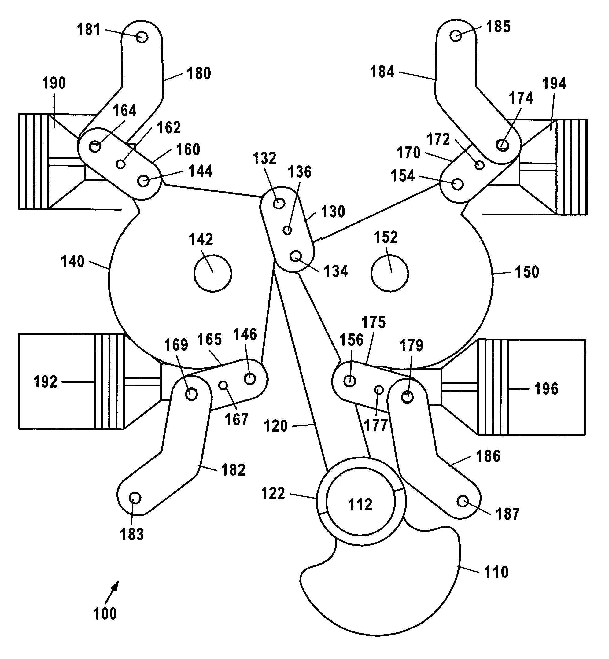
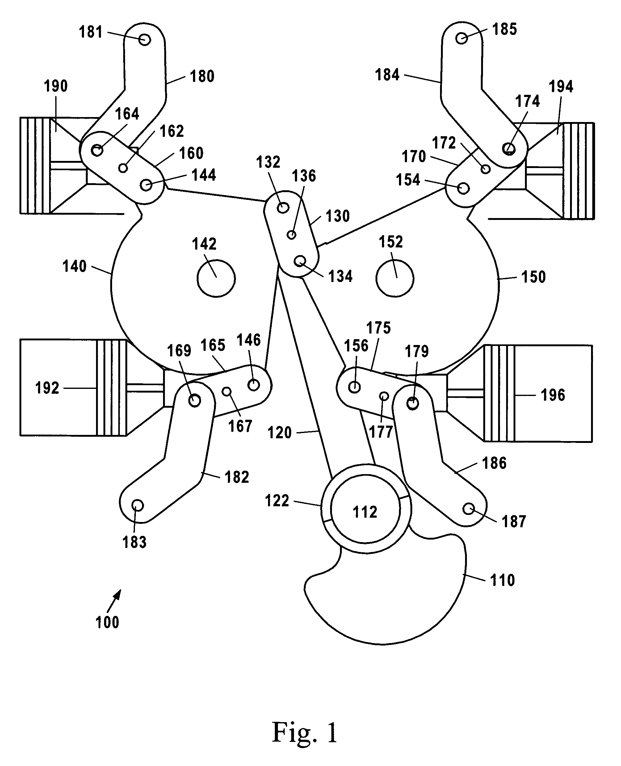
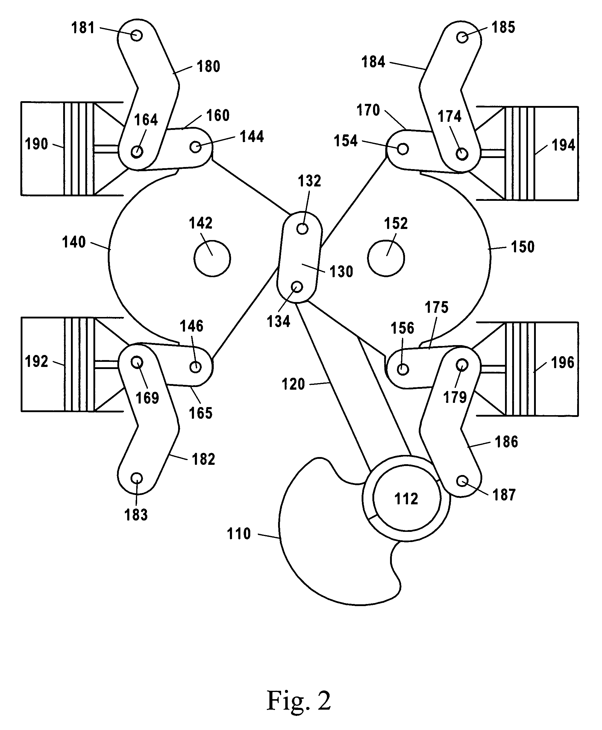
[0041]FIGS. 1-3 are views of one embodiment of a force transfer mechanism 100 according to the present invention. Force transfer mechanism 100 comprises a three-arm bell crank 140 driven by pistons 190 and 192 and another three-arm bell crank 150 driven by pistons 194 and 196. FIG. 1 shows pistons 190 and 194 at top dead center and pistons 192 and 196 at bottom dead center. FIG. 2 shows eac...


PUM


Abstract

A multiple watt-linkage force transfer mechanism is provided for an internal-combustion engine. The force transfer mechanism comprises two “bell cranks” that are used to drive a single crankshaft through a watt linkage mechanism. Each bell crank, in turn, is driven by two pistons through corresponding watt linkage mechanisms. The watt linkages connected to the pistons enable the connection ends of the pistons to travel along substantially straight paths, significantly reducing side loads against the piston walls. Also, all four pistons preferably drive a single connecting rod. This changes the role of the crankshaft—and the corresponding strength and rigidity requirements for the crankshaft—by reducing the necessary number of rod journals and main journals on the crankshaft.

Description

FIELD OF THE INVENTION[0001]This invention relates to engines, and more particularly, but not limited to four-stroke internal combustion engines.BACKGROUND OF THE INVENTION[0002]To appreciate the advantages of the present invention, it is important to understand various aspects of how a typical internal combustion (IC) engine works.[0003]In a typical IC engine, where the cylinders are fixed with respect to the engine frame, the motion of the connecting rods create side forces on their corresponding pistons that push against the cylinder walls. A standard four-cylinder internal combustion engine comprises four pistons, a crankshaft, and four connecting rods, each having a “big end” and a “small end.” Each piston is connected to the crankshaft through a corresponding connecting rod. The “big end” of the connecting rod is connected to one of several “rod journals” on the crankshaft—also known as a “crank throw”—that is offset from the “main journals” of the crankshaft. The “small end” ...

Claims


Application Information

Patent Timeline
IPC IPC(8): F16C7/00
CPCF01B9/02F02B75/045F02B75/32
Inventor BRICKLEY, MICHAEL DENNIS
Owner BRICKLEY MICHAEL DENNIS
Why Eureka
Try Eureka