Method and structure for high performance phase change memory

a phase change memory and high-performance technology, applied in the field of phase change memory, can solve the problems of poor control of the switching process, low memory utilization rate, and loss of memory when the computer or the device is switched off, and achieve the effects of improving performance, speed and size, and high density properties

Active Publication Date: 2007-05-22
GLOBALFOUNDRIES US INC
View PDF7 Cites 68 Cited by
  • Summary
  • Abstract
  • Description
  • Claims
  • Application Information

AI Technical Summary

Benefits of technology

[0016]It is another exemplary feature of the present invention to provide a technique in which a faster, more efficient, and scalable PRAM memory cell can satisfy requirements in environments not previously realistic for PRAM.
[0019]In a third exemplary aspect of the present invention, described herein is a method of increasing performance in a phase change material (PCM) memory cell, including using a thin surface layer of the PCM as a storage for an information bit.
[0021]Thus, the present invention provides improved performance, speed, and size over conventional PRAM devices and presents an advantageous new technology that is very promising as a storage class memory.
[0022]Moreover, a high performance PRAM, such as taught by the present invention, is suitable as a local nonvolatile memory embedded in the logic chip environment, e.g., as L3 cache. In this application, following a run interruption, the exact logic state of the system can be restored, enabling seamless continuation of the interrupted task, an advantage not provided by DRAM.
[0023]A second exemplary application is in hand-held devices, such as portable computers such as laptops, cell phone, portable audio / video devices, etc., where the nonvolatile and high density properties of PRAM enable it to replace the compact disk, thereby enhancing additional miniaturization of these types of devices for which compactness is highly desired by consumers.

Problems solved by technology

Dynamic random access memory (DRAM), the most widely used form of memory in computers, has several well-known disadvantages, including the characteristic that memory is lost when the computer or device is switched off.
DRAM is also relatively slow.
1. When the PCM is in the amorphous, high-resistance, state, passing significant current depends on an irreversible electrical breakdown-like conduction phenomenon. The control of this switching process is poor because of the non-linearity of this mechanism.
2. The geometry of the joule-heating based PRAM cell is not optimal for a high performance PRAM.
3. The irreversible conduction approach is only supported by a narrow range of GST compositions.
4. There is no simple scaling law.

Method used


Image

  • Method and structure for high performance phase change memory
  • Method and structure for high performance phase change memory
  • Method and structure for high performance phase change memory

Examples


Embodiment Construction

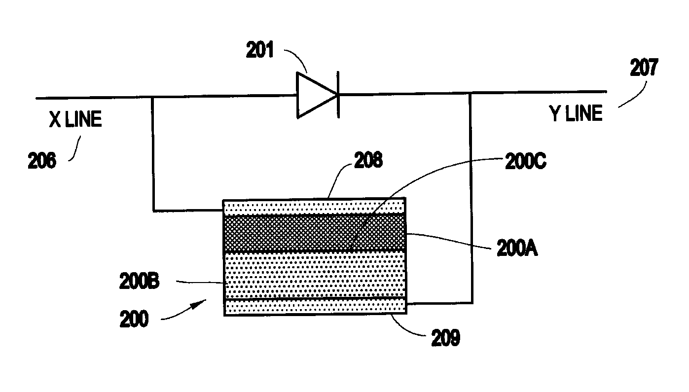
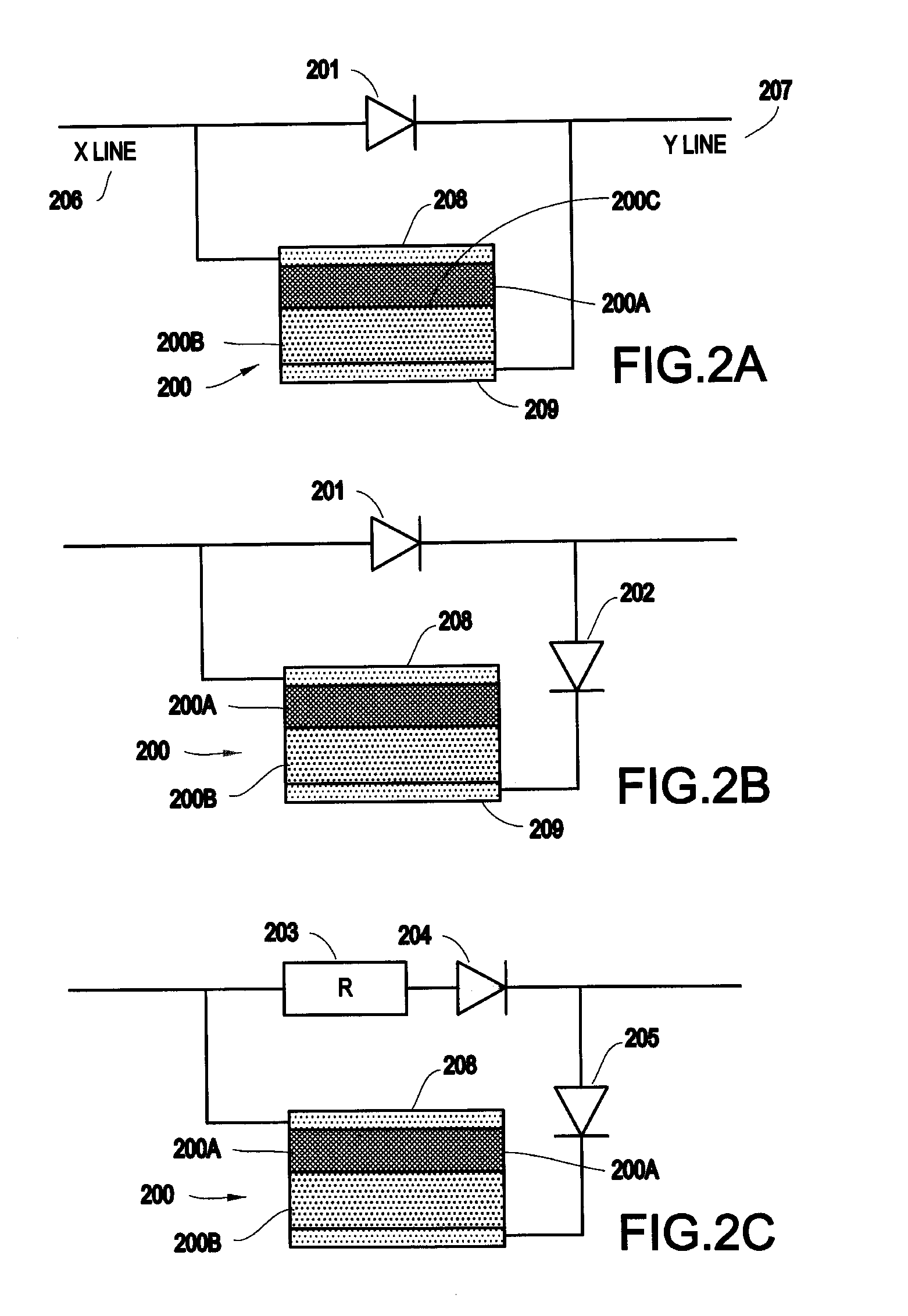
[0043]Referring now to the drawings, and more particularly to FIG. 2a through FIG. 18, exemplary embodiments of the present invention will now be described.

[0044]It is noted that one of ordinary skill in the art, after having read the details described herein, would readily be able to recognize the present invention as a broad concept in which a thin layer (e.g., within a range of about 2 to about 10 nanometers) within a PCM having a larger total thickness (e.g., about 50 nm or more), highly controllable by using an external heating element, provides the mechanism to provide drastic improvement in switching speed for PRAM.

[0045]In the context of the present invention, the term “nanoscopic” is intended as meaning a dimension of 100 nm or less. Thus, a concept of the present invention is that an information bit can be stored in only a nanoscopically thin surface layer of a PCM layer that has a thickness relatively larger than the thin surface layer of the that is of the PCM that is us...


PUM


Abstract

A method (and structure) for a memory cell having a phase change material (PCM) element and a heating element external to the PCM element. The heating element causes one of a presence of and an absence of a phase boundary within the PCM element for storing information in the PCM element.

Description

BACKGROUND OF THE INVENTION[0001]1. Field of the Invention[0002]The present invention generally relates to phase change memory, typically referred to as PRAM. More specifically, a heater element external to a phase change material (PCM) element, in combination with using only a thin layer of the PCM element for storing the information state of the memory unit, greatly improves speed and controllability.[0003]2. Description of the Related Art[0004]Up until the advent of the present invention described herein, phase change memory (phase change random access memory or PRAM) has been considered as a relatively slow, but nonvolatile, form of memory in a similar category to FLASH memory. It would be highly desirable to design a PRAM which has a much higher performance and is capable of competing as a nonvolatile memory in the role of DRAM, including embedded applications.[0005]Dynamic random access memory (DRAM), the most widely used form of memory in computers, has several well-known dis...

Claims


Application Information

Patent Timeline
Patent Type & Authority Patents(United States)
IPC IPC(8): G11C13/04
CPCG11C13/0004G11C13/003G11C13/0069H01L45/06H01L45/1233H01L45/126H01L45/1286H01L45/144H01L27/2409G11C2013/008G11C2213/72G11C2213/74G11C2213/79H10B63/20H10N70/231H10N70/826H10N70/8413H10N70/8613H10N70/8828
Inventor KRUSIN-ELBAUM, LIALUDEKE, RUDOLFNEWNS, DENNIS M.RAOUX, SIMONE
Owner GLOBALFOUNDRIES US INC
Why Eureka
Try Eureka