Sealing in a hydraulic turbine unit

a technology of hydraulic turbine unit and sealing, which is applied in the direction of climate sustainability, leakage prevention, bearings, etc., can solve the problems of not being able to use them between components, and achieve the effect of simple and reliable way

Inactive Publication Date: 2007-05-29
GITTLER PHILIPP
View PDF29 Cites 14 Cited by
  • Summary
  • Abstract
  • Description
  • Claims
  • Application Information

AI Technical Summary

Benefits of technology

[0017]The purpose of the invention is to provide a seal which, in all the hydraulic turbomachines mentioned in the intr

Problems solved by technology

Hydrostatic bearings in machine building and, in particular, in hydrodynamic machine building are known per se, but it has not been possible hitherto to use them between components, o

Method used


Image

  • Sealing in a hydraulic turbine unit
  • Sealing in a hydraulic turbine unit
  • Sealing in a hydraulic turbine unit

Examples


Embodiment Construction

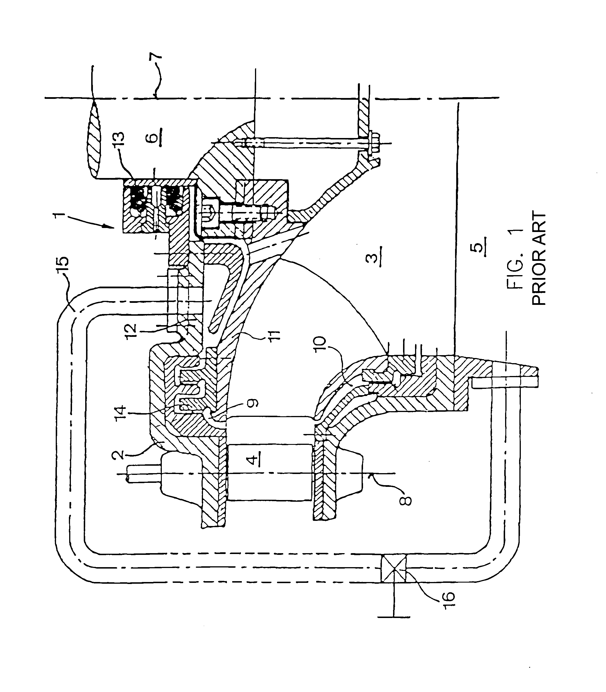
[0042]FIG. 1 shows diagrammatically a Francis turbine 1 according to the prior art, such as may be gathered from the book: “Rabe, Hydraulische Maschinen und Anlagen” (“Rabe, Hydraulic Machines and Plants”):

[0043]A rotor 3 rotates in a casing 2, the entry of the water taking place by way of a guide wheel 4 or its individual blades which are arranged rotatably, but with a fixed axis 8, in the casing 2. The rotor 3 has individual ducts which run in a curved manner both in the circumferential direction and with respect to the turbine axis 7, so that the water leaves the rotor 3 downwards essentially in the axial direction into the suction pipe 5.

[0044]Between the stationary casing 2 and the rotor 3, there are, of course, an upper gap or gap space 9 and a lower gap or gap space 10. The lower gap 10 leads to the loss of the gap water which passes into the region of the suction pipe, without the energy contained in it being capable of being worked off, but, apart from this loss, does not p...


PUM


Abstract

System for providing sealing between a rotor and a turbine casing in a hydraulic turbomachine includes a sealing ring arranged in a peripheral region of the rotor. The sealing ring forms at least one hydrostatic bearing with respect to at least one of the rotor and the turbine casing. The at least one hydrostatic bearing includes at least two bearing surfaces which face one another. At least one of the at least two bearing surfaces is arranged on the sealing ring. At least another of the at least two bearing surfaces is arranged on at least one of the rotor and the turbine casing. At least one groove is formed on at least one of the at least two bearing surfaces. At least one pressure-liquid line is coupled to each of the at least one groove and a pressure-liquid supply. This Abstract is not intended to define the invention disclosed in the specification, nor intended to limit the scope of the invention in any way.

Description

CROSS-REFERENCE TO RELATED APPLICATIONS[0001]The present application is a National Stage Application of International Application No. PCT / AT01 / 00293, filed Sep. 14, 2001. Further, the present application claims priority under 35 U.S.C. § 119 of Austrian Patent Application Nos. A 1581 / 2000 filed on Sep. 15, 2000 and A 278 / 2001 filed on Feb. 22, 2001.BACKGROUND OF THE INVENTION[0002]1. Field of the Invention[0003]The invention relates to the sealing-off of the rotor of hydraulic turbomachines, such as turbines, pumpturbines, accumulator pumps or other pumps, with respect to the turbine casing.[0004]2. Discussion of Background Information[0005]Kaplan turbines for low, Francis turbines for medium and Pelton turbines for high fall heights form the modem standard repertoire in the field of turbine construction. Francis turbines in this case cover essentially the fall-height range of between 30 m and 400 m.[0006]In this context, Francis turbines reach efficiencies of about 95% in the lower...

Claims


Application Information

Patent Timeline
IPC IPC(8): F16C32/06F01D11/04F16J15/40F03BF03B11/00F03B11/06F16J15/34F16J15/44
CPCF03B11/006F16J15/342F16J15/441F16C32/06F05B2240/53Y02E10/226Y02E10/20F03B11/00F16J15/34F16J15/44
Inventor GITTLER, PHILIPP
Owner GITTLER PHILIPP
Why Eureka
Try Eureka