Image signal correction light source that can cope with dust and scratch on transparent document, and its control

Inactive Publication Date: 2007-05-29
CANON KK
View PDF9 Cites 11 Cited by
  • Summary
  • Abstract
  • Description
  • Claims
  • Application Information

AI Technical Summary

Benefits of technology

[0015]The present invention has been made in consideration of the above situation, and has as

Problems solved by technology

However, since the surface light source as an indirect illumination system has poor illumination efficiency, a method of synchronously moving an illumination system and optical system is known so as to read an image at higher speed and with higher image quality.
However, it is often difficult to accurately detect position information of dust, scratches, and the like on a film.
However, positional deviation

Method used


Image

  • Image signal correction light source that can cope with dust and scratch on transparent document, and its control
  • Image signal correction light source that can cope with dust and scratch on transparent document, and its control
  • Image signal correction light source that can cope with dust and scratch on transparent document, and its control

Examples


first embodiment

[0044]

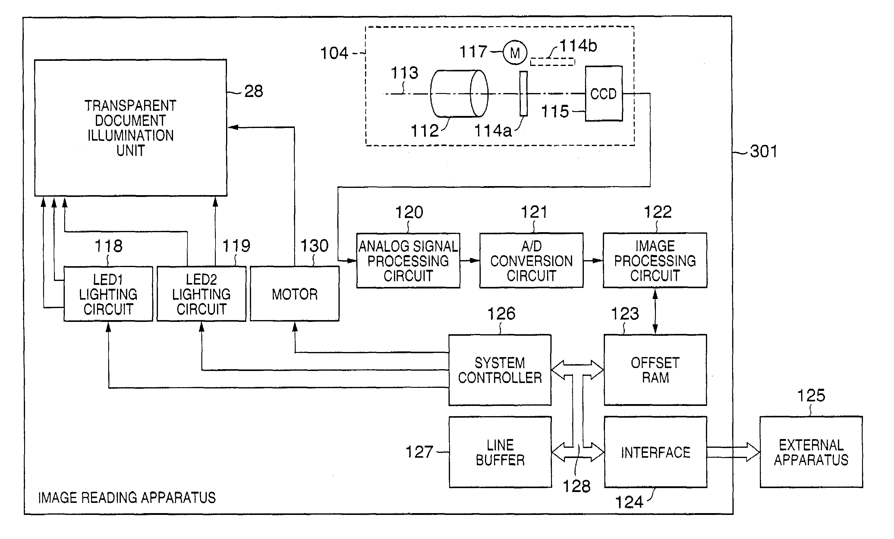
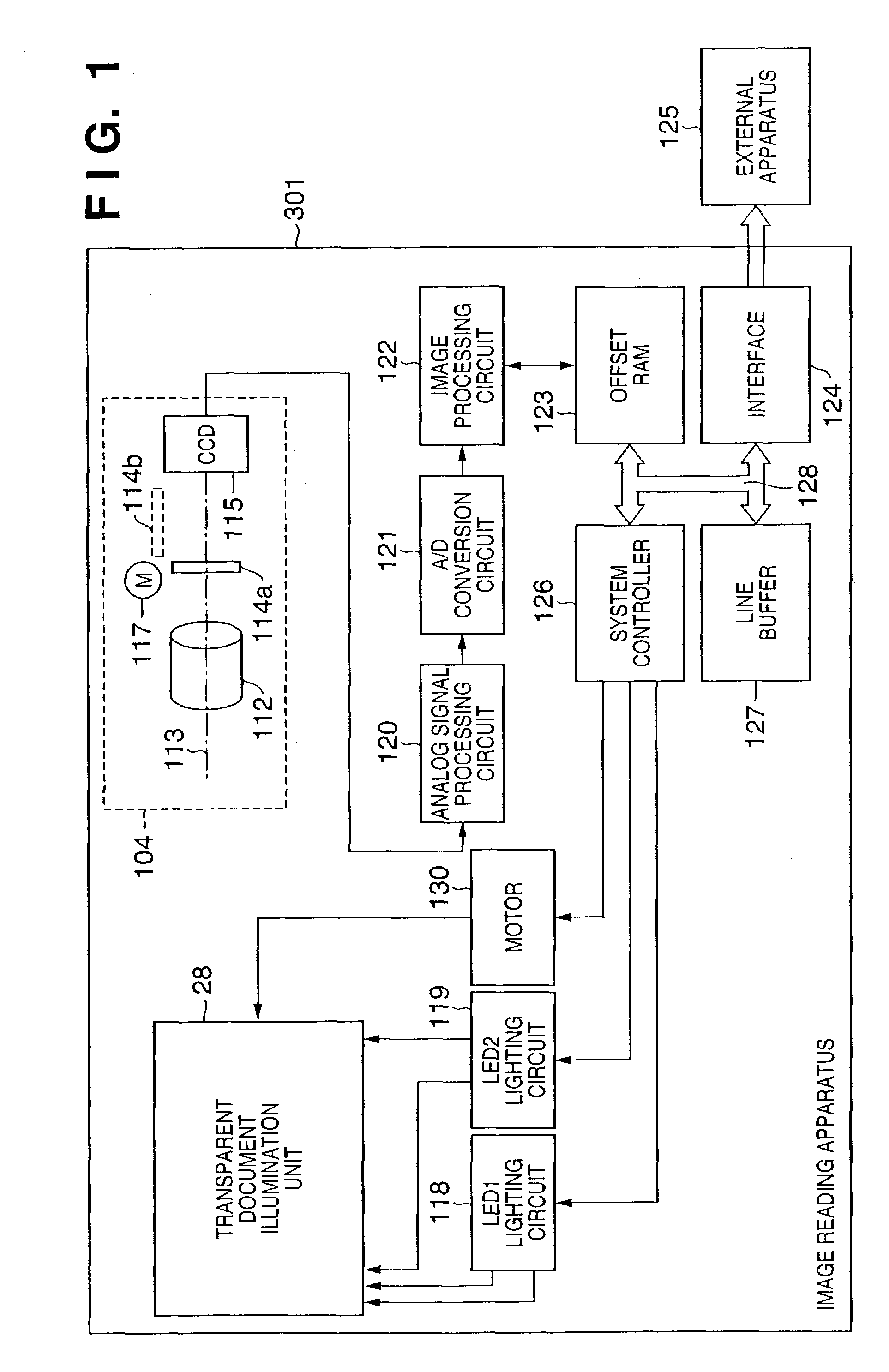
[0045]FIG. 1 is a block diagram showing the system arrangement which comprises an image reading apparatus 301 according to the first embodiment. Referring to FIG. 1, reference numeral 104 denotes an optical system unit which is formed on the side of a scanner main body; 112, an imaging lens which forms an optical image of light that has been transmitted through a transparent document; 113, an optical axis that passes through the center of the imaging lens; and 114, a glass plate used to correct the optical path length difference caused by the wavelength difference between visible light and infrared light. Reference numeral 114a denotes a state wherein the glass plate is placed parallel to a plane nearly perpendicular to the optical axis 113; and 114b, a state wherein the glass plate 114a is rotated through about 90° to escape from the optical path of an optical image. These states are controlled by a glass plate control motor 117. Reference numeral 115 denotes a CCD linear ima...

second embodiment

[0063]FIG. 5 shows the second embodiment of the LED array 29 on which LED1 elements which correspond to an LED light source used to read image information, and infrared LED2 elements which correspond to a light source used to detect dust / scratch information are arranged on nearly 1 Line in the main scan direction.

[0064]The LED1 and LED2 elements are respectively arranged at pitches d3 and d4 and can independently undergo ON / OFF control. In FIG. 5, the present invention can be practiced without limiting the number of LED elements.

[0065]Note that the pitches d3 and d4 need not be fixed, and may be freely set based on design causes such as the light amount level, homogeneity in the main scan direction, and the like. Note that the LED1 elements can use a plurality of types of LEDs such as R, G, B, white, and the like.

[0066]With the layout shown in FIG. 5 as well, the light amount distribution L1b formed by LED1, and the light amount distribution L2b formed by LED2 can be made nearly equ...

third embodiment

[0067]In FIG. 6, Motor HSYNC indicates a period signal for 1 Line to be scanned by the motor 130.

[0068]The accumulation time (CCD Shift gate pulse period) of the CCD image sensor 115 is divided into, e.g., four periods in 1 Line, as shown in FIG. 6, and a signal component as image information obtained by an ON / OFF control pulse of LED1, and a signal component as image information obtained based on a relative ON time based on an ON / OFF control pulse of LED2 are alternately obtained in line sequence as CCD output signals in these periods. By averaging or adding CCD image sensor outputs corresponding to signal components of each LED, positional deviation of image information can be mostly removed.

[0069]In FIG. 6, even when positional deviation is too large to ignore the difference between the light amount distributions of LED1 and LED2 shown in FIG. 2 or 5, or when the difference between the output levels of the LED elements is large, the ON time of LED1 can be controlled as L11 and L1...


PUM


Abstract

In a method of controlling an image reading apparatus, which has an illumination unit adapted to irradiate an object with first and second light rays in different frequency ranges, and a light-receiving unit adapted to receive light coming from the object, and to output a signal, and reads an image of the object by moving the illumination unit and light-receiving unit relative to the object, the light-receiving unit outputs a first signal in response to irradiation with the first light ray, and outputs a second signal in response to irradiation with the second light ray. Upon reading image information for one line by the image reading apparatus, the second light ray is controlled to be sequentially turned on at a plurality of timings to sandwich the ON timing of the first light ray, and image signals for one line corresponding to the first and second light rays are obtained by averaging or adding respective pieces of image information obtained at the plurality of timings for each of the first and second signals.

Description

FIELD OF THE INVENTION[0001]The present invention relates to a technique for reading information on a transparent document such as a photo film or the like, and correcting defects caused by, e.g., dust and scratches in an image by processing the read image signal.BACKGROUND OF THE INVENTION[0002]In recent years, along with the development of communication networks, high-speed computers, and large-size storage media, higher image quality is demanded upon handling color image information. Above all, a demand for accurately reading color image information at high speed and with high image quality using a scanner or the like is increasing.[0003]Also, upon reading an image on a photo film, a demand for accurately reading photo film image information of a sleeve form having a plurality of frames at high speed and with high image quality is increasing. In order to read a film image with higher image quality, an image reading apparatus having dust / scratch removal processing unit on a film h...

Claims


Application Information

Patent Timeline
IPC IPC(8): H04N1/03H04N1/04H04N1/191H04N1/00H04N1/409
CPCH04N1/00002H04N1/00023H04N1/00037H04N1/0005H04N1/00082H04N1/00092H04N1/4097H04N2201/0408
Inventor HANABUSA, MITSUGUTAKAYAMA, TSUTOMU
Owner CANON KK
Why Eureka
Try Eureka