Nip width sensing system and method

a technology of width sensing and nip, applied in the direction of instruments, machines/engines, force/torque/work measurement apparatus, etc., can solve the problems of uneven surface characteristics, fiber crushing as well as holes in the resulting paper product,

Inactive Publication Date: 2007-06-05
U S BANK NAT ASSOC
View PDF39 Cites 46 Cited by
  • Summary
  • Abstract
  • Description
  • Claims
  • Application Information

AI Technical Summary

Problems solved by technology

Excessive pressure can cause crushing of fibers as well as holes in the resulting paper product.
Conventional methods addressing this problem have been inadequate and, thus, this problem persists in the press section, often resulting in paper of poor quality, having uneven surface characteristics.
Roll deflection, commonly due to sag or nip loading, is a source of uneven pressure distribution.
Notwithstanding the problem of roll deflection, the problem of uneven loading across the roll length and in the cross machine direction persists because pressure is often unevenly applied along the roll.
One of the major difficulties in using the nip impression procedure is that of evenly loading the rolls from front to back.
This process is cumbersome, time consuming, and generally inefficient.
Furthermore, the Prescale films are not reusable.
Lastly, the Prescale films are temperature and moisture dependent, thus leading to inaccurate and unreliable results.
These measurements are time consuming and are subject to operator variations.
Thus, the processing may continue at a less than optimal state.
Thus, the interpretation times are not improved.
This method has the advantage of reusability, but is subject to the same loading path challenges in that it will record the greatest contact width and not necessarily the final stable state.
Because this technique does not provide nip width measurements, it is inconvenient to use to make crown corrections.
The method provides discrete load reading across the machine, but does not produce nip width measurements.

Method used


Image

  • Nip width sensing system and method
  • Nip width sensing system and method
  • Nip width sensing system and method

Examples


first embodiment

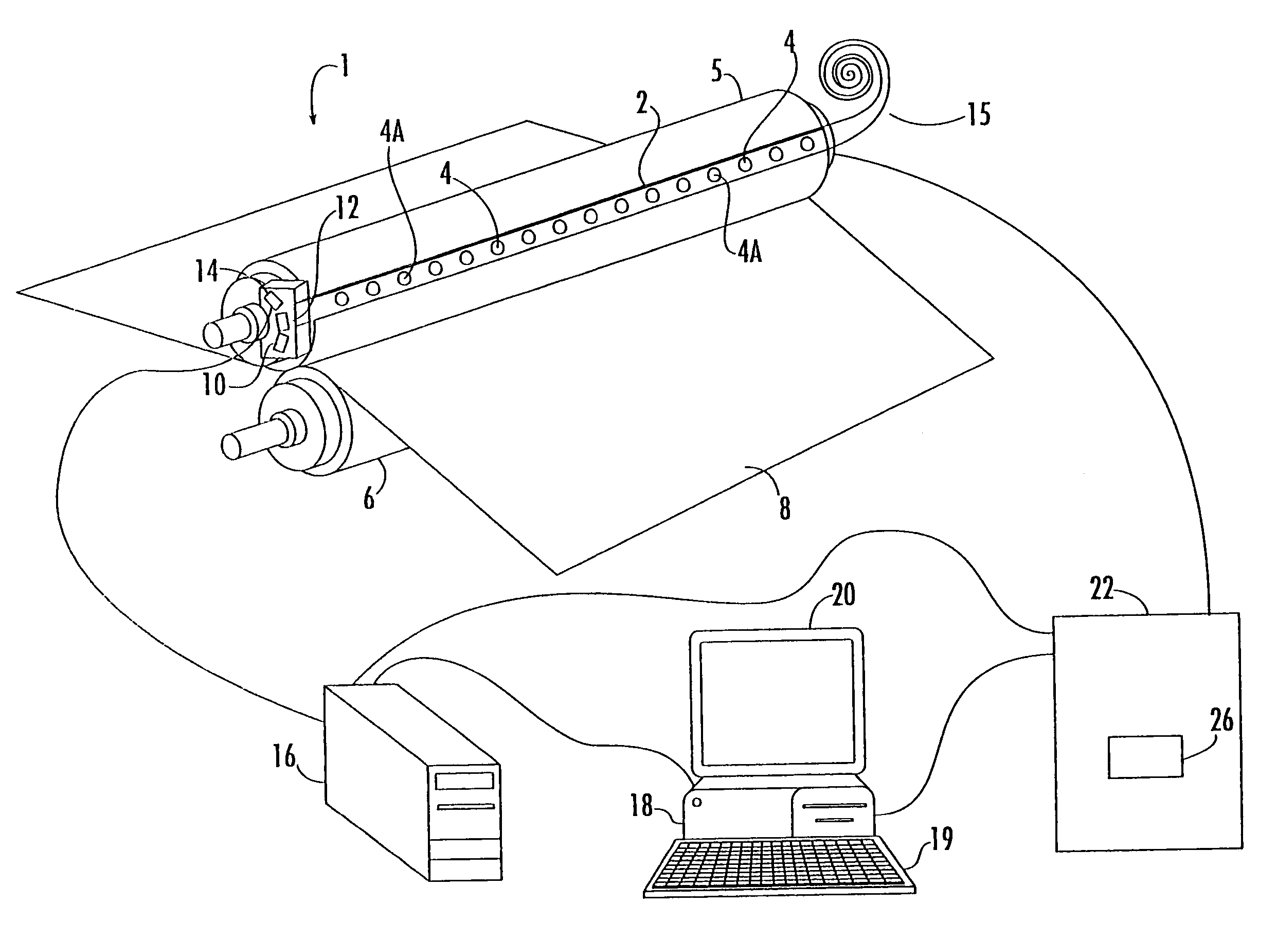
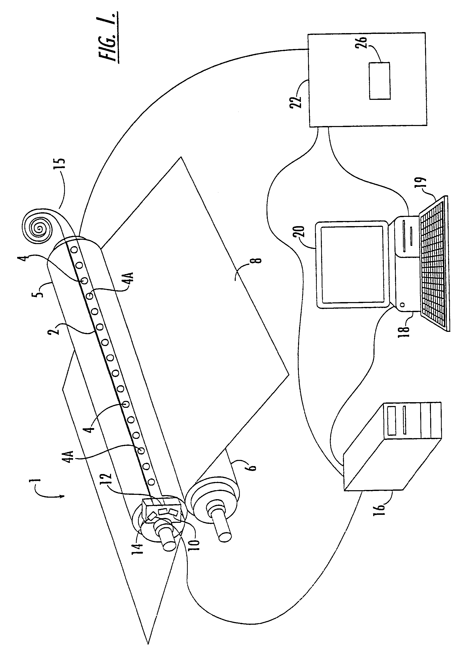
[0124]With reference to FIGS. 9 and 10, a sensor 30 is shown therein. Sensors 30 of this construction may be used in the sensing system 1 as the sensors 4. The sensor 30 is what is commonly referred to as a force sensitive resistor sensor or FSR sensor. The sensor 30 includes spaced apart electrically conductive, flexible, resilient strips 32 and 34 which may be formed of silver or like material. Lead lines L1 and L2 are connected to the strips 32 and 34, respectively, and to the resistance measuring means. The strips 32 and 34 have layers 32A and 34A of resistive material secured to their opposed faces. The opposed faces of the layers 32A and 34A are separated by an air gap 36 and have substantially complementary, rugged profiles. Examples of suitable FSR sensors include UNIFORCE™ sensors available from Force Imaging Technologies, Inc. of Chicago, Ill.

[0125]The sensor 30 has an effective sensor length SL which is greater than the longest anticipated nip width to be measured. For e...

second embodiment

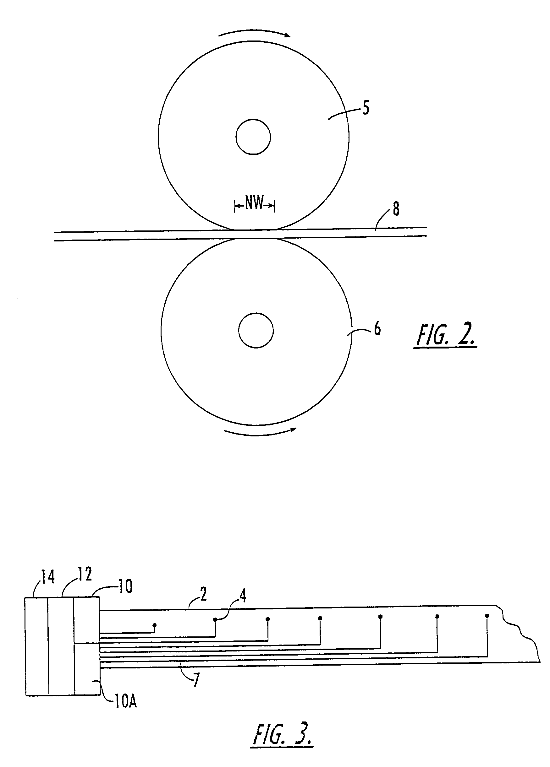
[0181]Referring now to FIGS. 11 and 12, a sensor 40 is shown therein mounted on the strip 2 (see FIG. 11) as one of the sensors 4. The sensor 40 has an effective sensing length SL extending from the leftmost to the rightmost vertical line 41A and an effective sensing width SW extending from the topmost to the lowermost horizontal line41B. Preferably, the sensor length SL is the same as described with respect to the sensor 30 and the sensor width is greater than the width of any grooves or drill holes in the roll. As in the case of the sensor 30, the sensor 40 employs a force sensitive resistive material. However, in the sensor 40, the force sensitive material is provided in a prescribed, discrete configuration which serves to minimize the effect of variations in nip pressure magnitude, thereby providing a more direct and accurate approximation of the nip width NW.

[0182]FIG. 11 schematically depicts the sensor 40 disposed on the strip 2 and spanning the nip width NW. FIG. 12 is a sc...


PUM

PropertyMeasurementUnit
thicknessaaaaaaaaaa
lengthaaaaaaaaaa
widthaaaaaaaaaa

Abstract

Devices for measuring a nip width between rolls of a press nip include one or more sensors adapted to be placed in the nip while the nip is stationary. The electrical resistance of each sensor corresponds to the size of the nip width, whereby a nip width or a nip width distribution may be determined by measuring the sensor resistance(s). Methods of measuring a nip width distribution include providing a plurality of force sensitive resistor sensors each of which respond to pressure applied thereto to provide a variable sensor resistance as a function of the amount of pressure and the area of the pressure exerted on the sensor.

Description

RELATED APPLICATION[0001]This application is a divisional application of and claims priority from application Ser. No. 10 / 444,289; filed May 23, 2003, now U.S. Pat. No. 6,769,314, which is a divisional of application Ser. No. 09 / 252,203, filed Feb. 18, 1999, issued on May 27, 2003 as U.S. Pat. No. 6,568,285, which claims priority from Provisional Application Ser. No. 60 / 075,237, filed Feb. 19, 1998.FIELD OF THE INVENTION[0002]The present invention relates to a system and method for use in connection with nipped rollers and rollers nipped with shoes such as those used in papermaking, steel making, plastics calendering and printing machines, and, more particularly, to such a system and method which are capable of determining the nip width distribution between the nipped rollers.BACKGROUND OF THE INVENTION[0003]Nipped rolls are used in a vast number of continuous process industries including papermaking, steel making, plastics calendering and printing. The characteristics of nipped rol...

Claims


Application Information

Patent Timeline
Patent Type & Authority Patents(United States)
IPC IPC(8): G01L5/00G01B7/06G01B7/14G01LG01L1/20
CPCG01B7/14G01L5/0085
Inventor MOORE, ROBERT H.KENNEDY, WILLIAM B.
Owner U S BANK NAT ASSOC
Why Eureka
Try Eureka