Elevated rail transportation system

a rail transportation system and elevated technology, applied in transportation and packaging, propulsion railway systems, transportation and packaging, etc., can solve the problems of high construction and operation costs, insufficient versatility of light rail transportation systems, and inability to use rapid transit systems, so as to reduce wear and operation noise, eliminate differential speeds, and reduce the effect of nois

Active Publication Date: 2007-06-05
FLIGHT RAIL CORP
View PDF5 Cites 3 Cited by
  • Summary
  • Abstract
  • Description
  • Claims
  • Application Information

AI Technical Summary

Benefits of technology

[0017]The wheels of the vehicle are inclined at a preferred angle of 45°. In this manner, the wheels are symmetric relative to the sides of the angle tracks. As a result, the wheels can be smooth and do not require the rims needed for conventional rails. This in turn eliminates differential speeds between different portions of the wheel and the track, thereby reducing wear as well as operational noise.

Problems solved by technology

Although there has been a general recognition of the need for a reliable, safe rapid transportation system, utilization of rapid transit systems has been hindered by the high cost of construction and operation as well as technical difficulties in developing an efficient and versatile light rail system.
Conventional approaches have not produced a light rail transportation system that is sufficiently versatile, efficient and cost-effective to be a feasible substitute for non-mass transportation and air travel alternatives.
For instance, some so-called light rail systems have rather heavy transportation modules due to the use of heavy undercarriage or a heavy power system, high traction requirements, high on-board fuel requirements, or the like.
Systems that rely on traction drives tend to have difficulty with steep grades.
Moreover, external elements such as severe weather conditions and contaminations can pose substantial difficulty in the operation and maintenance of light rail systems.
Additionally, traction drive mechanisms employing wheels tend to produce a lot of noise as well as wear.
Although the transportation systems disclosed in U.S. Pat. No. 6,360,670 B1, as well as in related U.S. Pat. No. 6,279,485 and in U.S. Pat. No. 6,267,058, which is also incorporated herein by reference, provide important advances for elevated rail transportation technology, actual tests and theoretical evaluations have shown that some of the components of the system which is the subject of these earlier U.S. patents have certain disadvantages such as, for example, excessive wear or friction, maintenance problems, and the like.

Method used


Image

  • Elevated rail transportation system
  • Elevated rail transportation system
  • Elevated rail transportation system

Examples


Embodiment Construction

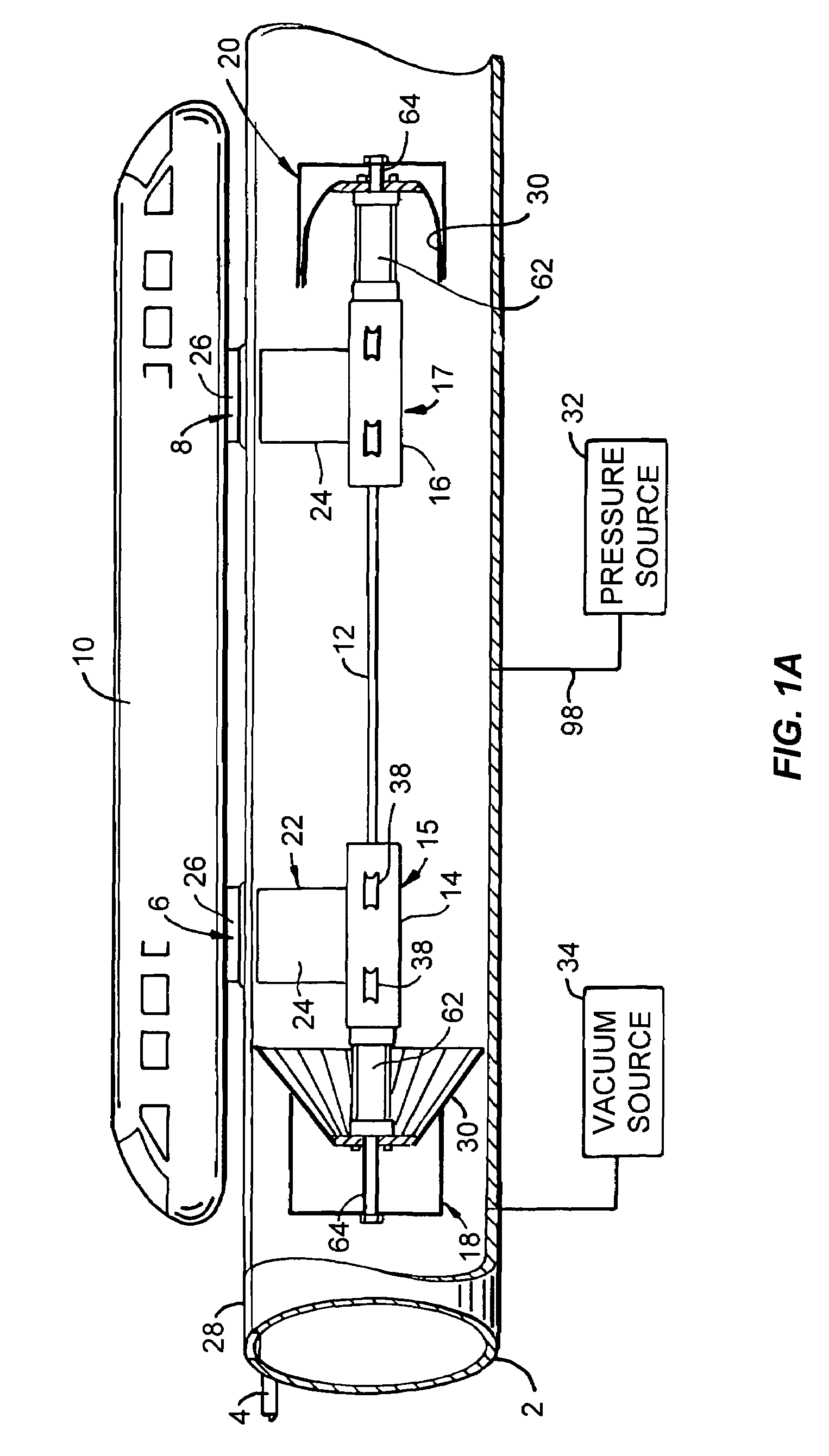
[0030]Referring first to FIG. 1A, a light rail transportation system constructed in accordance with the present invention includes an elongated power tube 2 which is suitably supported above ground, as is further described below. On its lateral sides proximate the top of the tube are a pair of parallel, spaced-apart angle tracks 4, the included angle of which faces outwardly relative to the power tube in the preferred embodiment of the invention, and which receive, support and guide wheels (not separately shown in FIG. 1A) carried on spaced-apart, e.g. forward and aft, undercarriages 6, 8, which in turn support, carry and guide a transportation vehicle 10 such as an illustrated passenger cabin or cargo wagon (not shown).

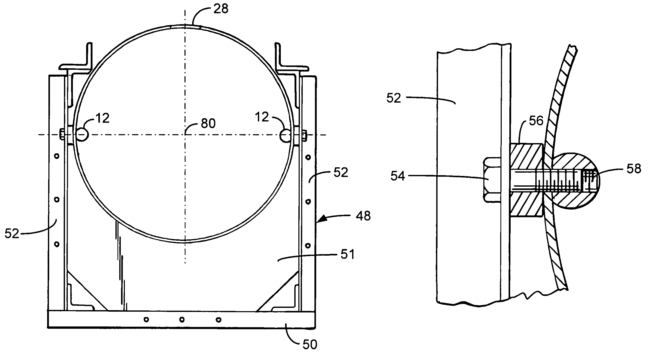
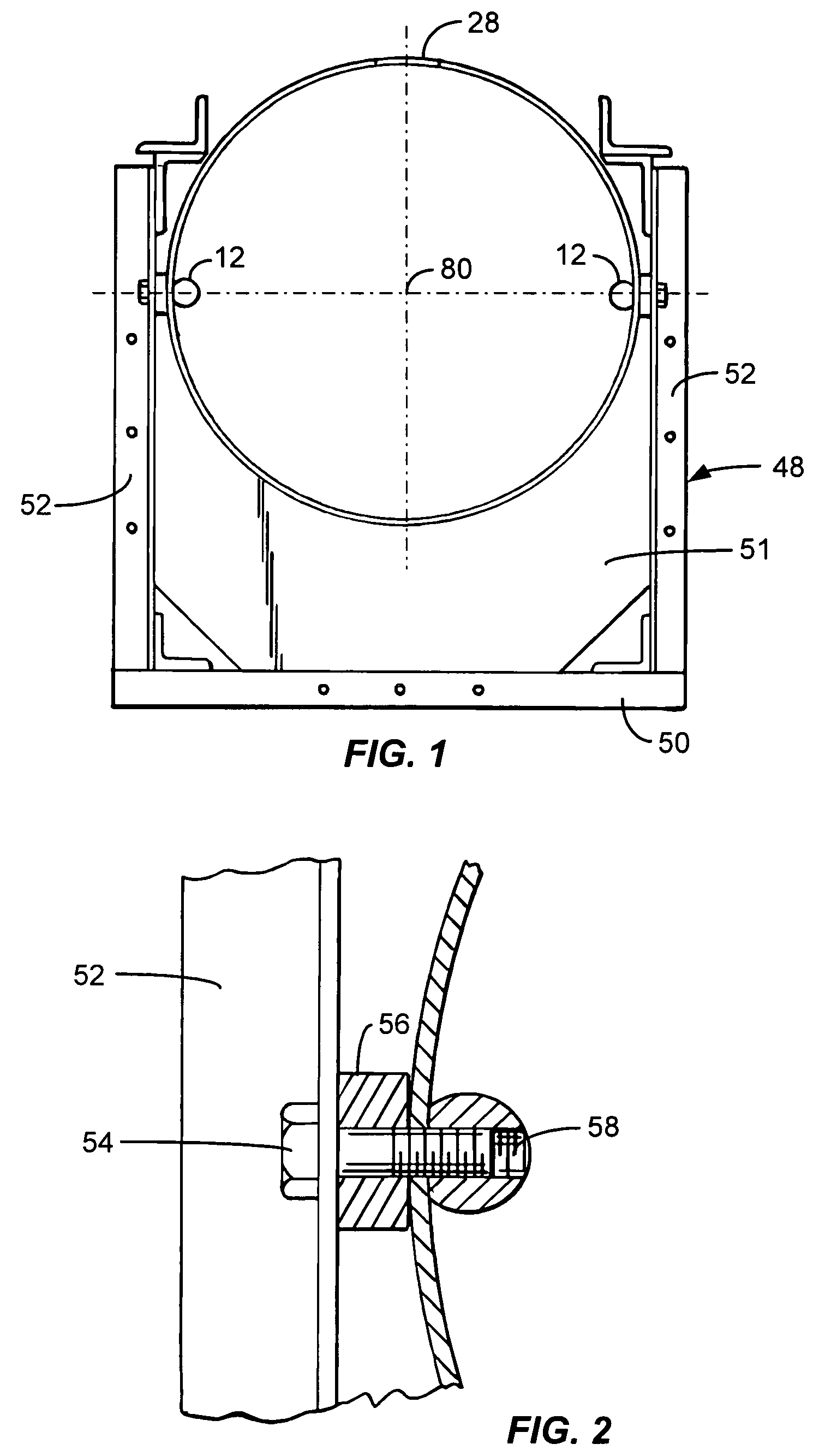
[0031]Inside the power tube and preferably aligned with the horizontal axis of the tube are opposing interior rails 12, in the form of elongated round bars attached to the power tube which extend over its length. First and second propulsion units 15, 17 are disposed ...


PUM


Abstract

A system for propelling a vehicle along an elevated, pneumatic power tube carried by exterior support structure above ground. First and second angles define tracks for the vehicle and extend parallel to the power tube. Undercarriages secured to the vehicle including vehicle support and guidance wheels which are rotatable about axes inclined relative to legs of the angle tracks have a periphery that engages the legs of the angle tracks so that the weight of the vehicle is supported by the tracks and the support structure only. A pneumatic propulsion unit is movably disposed inside the power tube and is guided along rails on the inside of the power tube. A magnetic coupler having first and second cooperating magnetic elements is attached to the vehicle and the propulsion unit in operative alignment with each other. A portion of the power tube located between the magnetic elements is constructed of a non-magnetic and non-conductive material and extends over the length of the power tube. The propulsion unit has a thrust carriage with a thrust valve that forms a collapsible, frusto-conically shaped wall formed by a multiplicity of overlapping, angularly inclined blades that are concentrically disposed in the power tube. An actuator is coupled to the blades for selectively increasing an angle of the blades until free ends thereof contact an interior surface of the power tube, to thereby prevent the flow of air through the tube past the wall, and for retracting the blades so that the free ends thereof are spaced apart from the interior surface of the power tube, the valve generating a force acting in the longitudinal direction of the power tube when the free ends of the valve blades engage the interior surface.

Description

CROSS-REFERENCES TO RELATED APPLICATIONS[0001]This application claims the priority and is a continuation of U.S. provisional patent application No. 60 / 476,486 filed Jun. 5, 2003.BACKGROUND OF THE INVENTION[0002]Rapid mass ground transportation systems offer many benefits over non-mass transportation means such as the use of automobiles, particularly in metropolitan areas experiencing severe traffic congestion and pollution problems. Mass ground transportation may also be a desirable alternative for short-range as well as long-range air travel. Although there has been a general recognition of the need for a reliable, safe rapid transportation system, utilization of rapid transit systems has been hindered by the high cost of construction and operation as well as technical difficulties in developing an efficient and versatile light rail system.[0003]Conventional approaches have not produced a light rail transportation system that is sufficiently versatile, efficient and cost-effective ...

Claims


Application Information

Patent Timeline
Patent Type & Authority Patents(United States)
IPC IPC(8): B61B13/00B61B13/12
CPCB61B13/122
Inventor SCHLIENGER, MAX P.
Owner FLIGHT RAIL CORP
Why Eureka
Try Eureka