Drop tube assembly

a technology of drop tube and assembly, which is applied in the direction of liquid transfer device, liquid handling, packaging goods type, etc., can solve the problems of telescoping drop tube configuration, affecting the operation of the drop tube, and a history of cold weather sticking problem, so as to improve the problem of cold weather sticking and increase the radial clearance

Active Publication Date: 2007-06-05
MARATHON PETROLEUM
View PDF9 Cites 8 Cited by
  • Summary
  • Abstract
  • Description
  • Claims
  • Application Information

AI Technical Summary

Benefits of technology

[0008]As a result, we developed a novel drop tube loading arm assembly. The assembly especially is adaptable for loading asphalt into tank trailers at marketing terminals. The telescoping drop tube employs placed guides made of aluminum or polymers such as fluorocarbon polymers and strategically placed aluminum guides. The guides are located in the annular space between concentric tubes. This in combination with increased radial clearance between the tubes or sleeves and in combination with protection for the overfill probe, has greatly improved the cold weather sticking problem.

Problems solved by technology

Asphalt loading arms have a history of cold weather sticking problems.
With the addition of vapor control systems and overfill protection probes, the telescoping drop loading spout configuration became more complex.
In colder weather, sticking problems occurred due to the smaller annular clearances.
Other problems surfaced as well.

Method used


Image

  • Drop tube assembly
  • Drop tube assembly
  • Drop tube assembly

Examples


Embodiment Construction

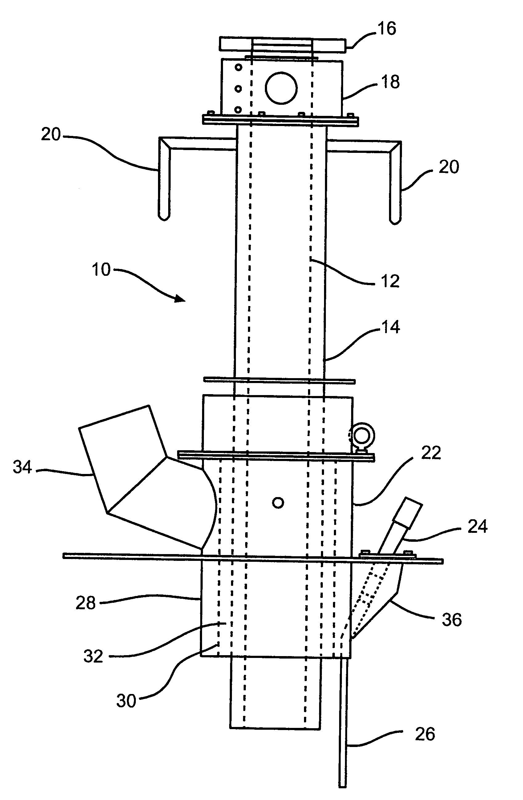
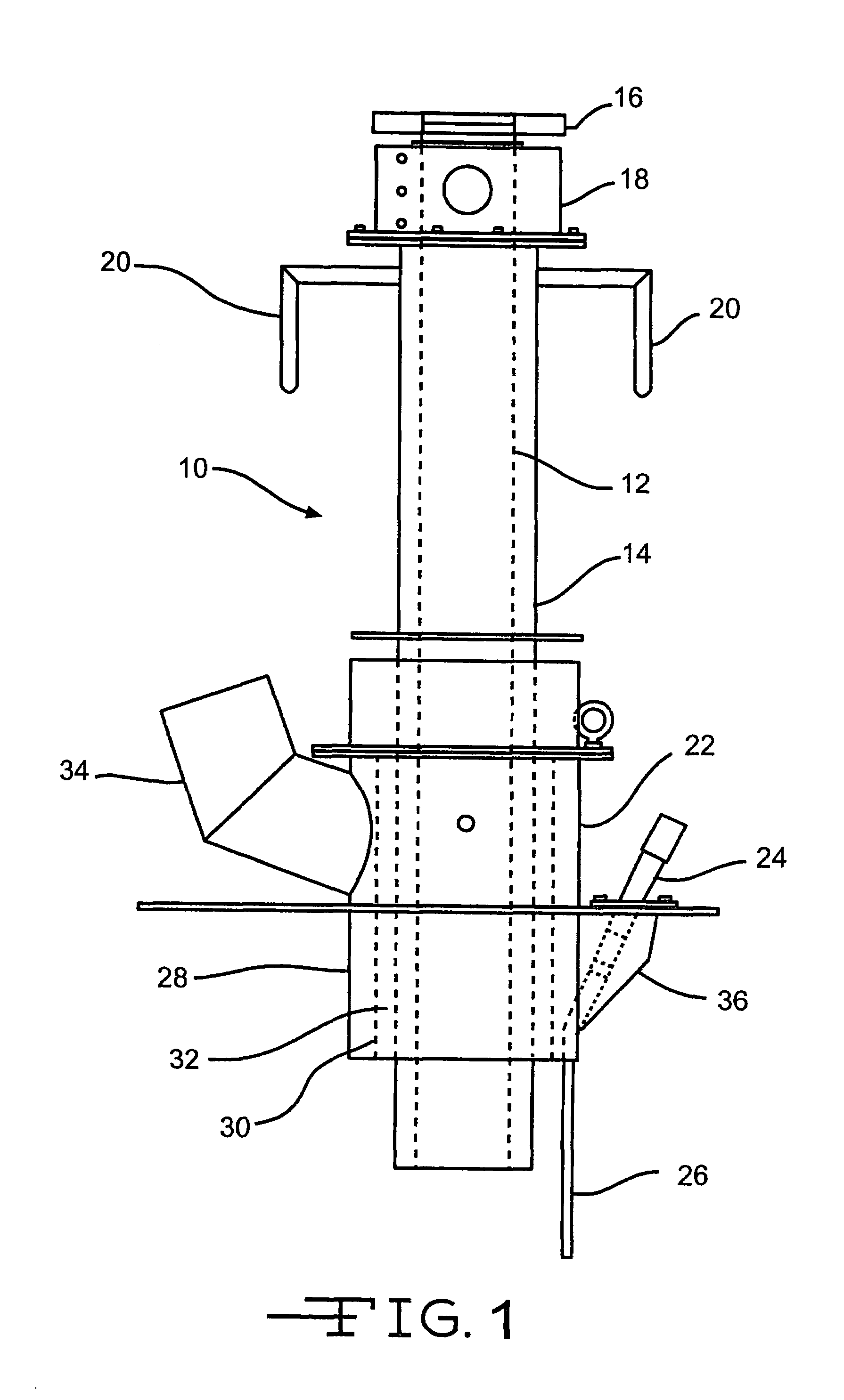
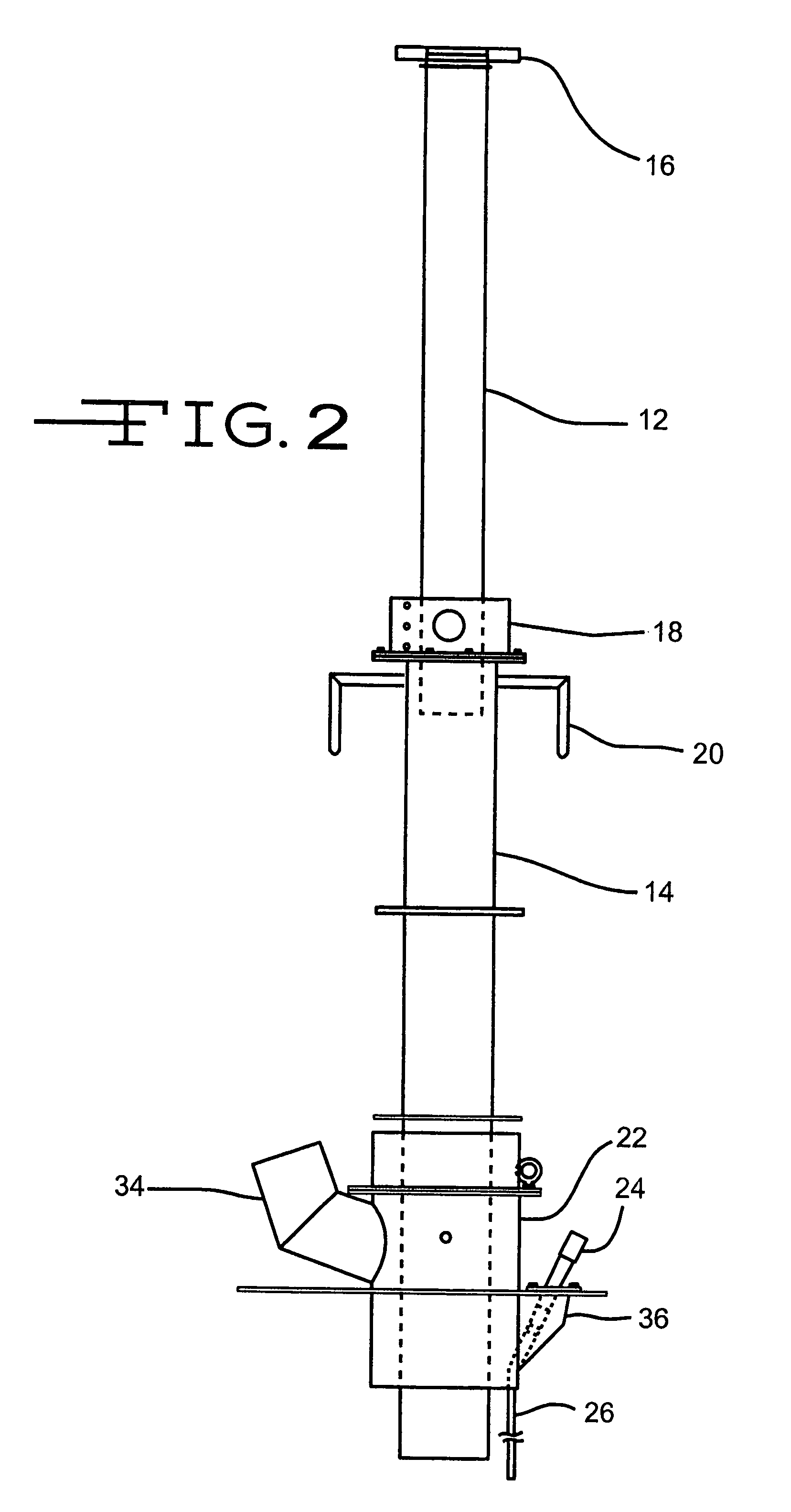
[0018]In a preferred embodiment, a glide rail is connected to the exterior of the first drop tube, and the second drop includes an annular slot, wherein the annular slot is slidably mounted against the glide rail. The assembly also includes circuitry and a monitor wherein the circuitry connects the fluid overfill detection probe to the monitor. A controller and its circuitry connects the controller between the monitor and the liquid source. A vapor recovery hose and a vapor recovery manifold as included wherein the vapor recovery hose connects the vapor recovery nozzle to the vapor recovery manifold. In another preferred embodiment, a protective plate connected to the spout to protect the fluid overfill detector probe.

[0019]The polyfluorocarbon polymer guide varies widely. Preferably, the guide is a polyfluorocarbon polymer. This term includes polytetrafluoroethylene (PTFE), polymers of chlorotrifluoroethylene, fluorinated ethylene-propylene and the like. The term also includes copo...


PUM

PropertyMeasurementUnit
lengthaaaaaaaaaa
timeaaaaaaaaaa
liquidaaaaaaaaaa

Abstract

This drop tube loading arm assembly is adaptable for loading asphalt into tank trailers at marketing terminals. The telescoping drop tube employs guides made of steel rollers of polymers such as fluorocarbon polymers and aluminum. The guides are located in the annular space between the tubes in combination with increased radial clearance between the tubes or sleeves and in combination with protection for the overfill probe. With the addition of vapor control systems and overfill protection probes, the telescoping drop loading spouts are less susceptible to cold weather sticking problems.

Description

CROSS REFERENCE TO RELATED APPLICATIONS[0001]This application is a continuation-in-part of U.S. patent application Ser. No. 10 / 894,373 filed Jul. 19, 2004 now U.S. Pat. No. 6,932,123.TECHNICAL FIELD OF THE INVENTION[0002]This invention relates to a drop tube loading arm assembly, for loading volatile liquid storage tanks such as fuel tanks and asphalt tanks.BACKGROUND OF THE INVENTION[0003]The present relates to volatile liquid storage tanks and more particularly to such tanks having apparatus for reducing vapor generation when the tank is filing from the upper or top side of the tank. These tanks could include asphalt terminals, tank trucks, above ground petroleum fuel tanks, chemical storage tanks, mobile liquid storage containers, and the like. The focus of this invention will be on filling tank trucks from asphalt terminals. The invention, however, has application with other tank types as well.[0004]Tanks can be mounted on tanker trucks or located underground at service stations...

Claims


Application Information

Patent Timeline
Patent Type & Authority Patents(United States)
IPC IPC(8): B65B1/04B67D7/04B67D7/36
CPCB67D7/0476B67D7/362
Inventor CRAIG, JONMALEC, MIKEHARMON, MIKEPULTER, JEFF
Owner MARATHON PETROLEUM
Why Eureka
Try Eureka