Methods and apparatus for forming rhodium-containing layers

a technology of rhodium-containing layers and methods, applied in the field of integrated circuits, can solve the problems of degrading the cell capacitor, degrading the series capacitance, and not delivering a layer sufficiently conformal for vlsi devices, and achieve excellent barrier protection, conformality, and conformality. high degree of conformality

Inactive Publication Date: 2007-06-05
MICRON TECH INC
View PDF115 Cites 8 Cited by
  • Summary
  • Abstract
  • Description
  • Claims
  • Application Information

AI Technical Summary

Benefits of technology

[0021]The chemical vapor deposited Pt—Rh co-deposited alloy layers of the invention provide excellent barrier protection, conductivity as capacitor electrodes, and conformality, and so may be employed either as capacitor electrodes, or as separate barrier layers formed adjacent to conventional capacitor electrodes, either atop these electrodes or interposed between the electrode and the capacitor dielectric. Preferably, the CVD Pt—Rh alloy layer according to the invention comprises a thin barrier layer between a cell dielectric and an underlying polysilicon (poly) plug or drain in a DRAM cell array, as well as acting as a lower electrode. The term “CVD platinum-rhodium alloy” herein means a material layer containing platinum and rhodium in the compositional ranges and having the characteristic high degree of conformality described herein.

Problems solved by technology

However, it is necessary to maintain a sufficiently high storage capacitance to maintain a charge at the refresh rates currently in use even as cell size continues to shrink.
Oxidation of the underlying Si will result in decreased series capacitance, thus degrading the cell capacitor.
However, PVD deposition does not deliver a layer which is sufficiently conformal for VLSI devices.

Method used


Image

  • Methods and apparatus for forming rhodium-containing layers
  • Methods and apparatus for forming rhodium-containing layers
  • Methods and apparatus for forming rhodium-containing layers

Examples


Embodiment Construction

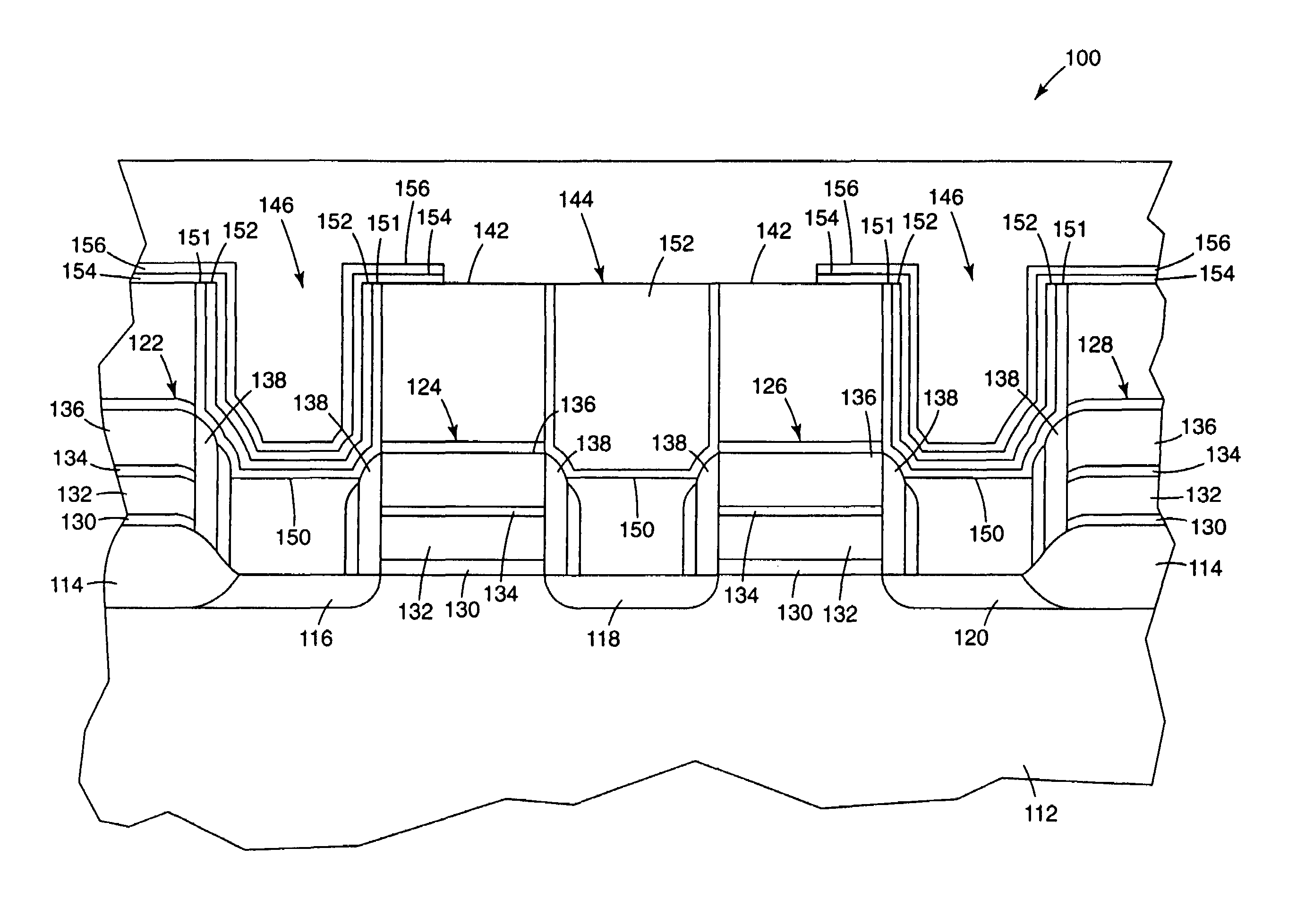
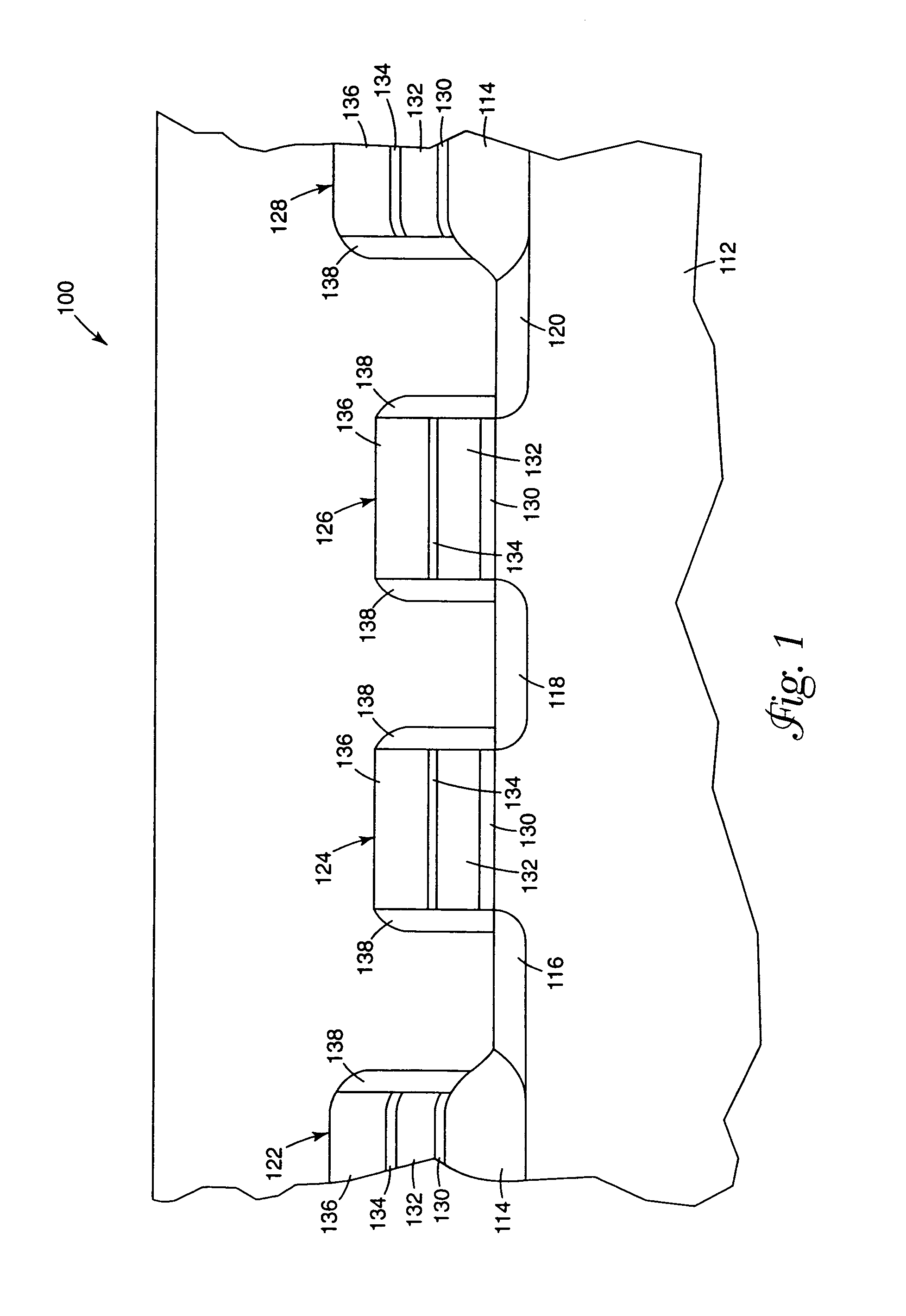
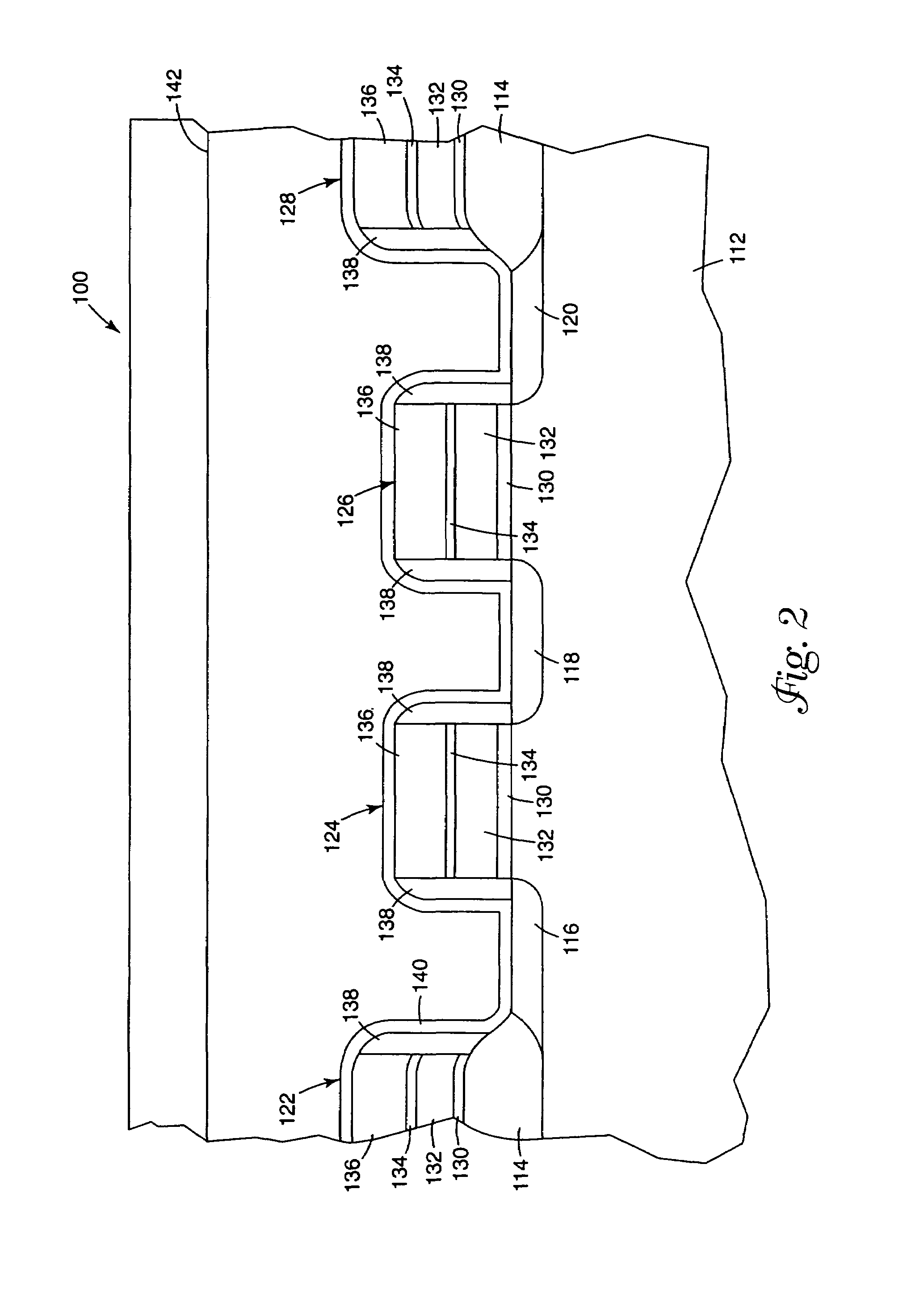
[0040]The present invention provides methods of forming a rhodium-containing layer, preferably an electrically conductive rhodium-containing layer, (e.g., pure rhodium, rhodium oxide, rhodium sulfide, rhodium selenide, rhodium nitride, or alloys of rhodium, particularly rhodium-platinum alloys, etc.). Specifically, the present invention is directed to methods of manufacturing a semiconductor device, particularly a ferroelectric device, having a rhodium-containing layer. The rhodium-containing layers formed are preferably conductive and can be used as barrier layers between the dielectric material and the silicon substrate in memory devices, such as ferroelectric memories, or as the plate (i.e., electrode) itself in the capacitors, for example. Because they are generally unreactive, such layers are also suitable for use in optics applications as a reflective coating or as a high temperature oxidation barrier on carbon composites, for example. They can be deposited in a wide variety o...


PUM

PropertyMeasurementUnit
temperatureaaaaaaaaaa
pressureaaaaaaaaaa

Abstract

A method of forming a rhodium-containing layer on a substrate, such as a semiconductor wafer, using complexes of the formula LyRhYz is provided. Also provided is a chemical vapor co-deposited platinum-rhodium alloy barriers and electrodes for cell dielectrics for integrated circuits, particularly for DRAM cell capacitors. The alloy barriers protect surrounding materials from oxidation during oxidative recrystallization steps and protect cell dielectrics from loss of oxygen during high temperature processing steps. Also provided are methods for CVD co-deposition of platinum-rhodium alloy diffusion barriers.

Description

CROSS-REFERENCE TO RELATED APPLICATION[0001]The present application is a divisional patent application of Ser. No. 09 / 651,699, Confirmation No. 2475, filed on Aug. 30, 2000 now U.S. Pat. No. 6,690,055, entitled DEVICES CONTAINING PLATINUM-RHODIUM LAYERS AND METHODS, which is a divisional of U.S. patent application Ser. No. 09 / 146,556, filed Sep. 3, 1998, issued as U.S. Pat. No. 6,271,131 on Aug. 7, 2001, which is a Continuation-in-Part of U.S. patent application Ser. No. 09 / 140,921, filed on Aug. 26, 1998 (abandoned).FIELD OF THE INVENTION[0002]The invention relates generally to integrated circuits and more particularly to the use of platinum-rhodium (Pt—Rh) alloy materials for electrodes and diffusion barrier layers to protect cell dielectrics in such circuits. The invention further relates generally to the preparation of rhodium-containing layers on substrates, particularly on semiconductor device structures.BACKGROUND OF THE INVENTION[0003]Layers of metals and metal oxides, parti...

Claims


Application Information

Patent Timeline
Patent Type & Authority Patents(United States)
IPC IPC(8): H01L21/44C23C16/16C23C16/18H01L21/02H01L21/285H01L21/3205H01L21/768H01L21/8242H01L27/108
CPCC23C16/16C23C16/18H01L21/28556H01L21/28568H01L21/32051H01L21/76843H01L21/7687H01L28/65H01L28/75H01L27/10811H01L27/10855H01L28/55H10B12/312H10B12/0335
Inventor UHLENBROCK, STEFANMARSH, EUGENE P.
Owner MICRON TECH INC
Why Eureka
Try Eureka