Bi-ventricular pacer, system and method

a technology of biventricular pacer and heart rate sensor, applied in the field of implantable heart rate monitoring device, can solve the problems of difficult detection of capture, and difficulty in capture detection, so as to increase the time period, and reduce the risk of fusion

Inactive Publication Date: 2007-06-05
ST JUDE MEDICAL
View PDF10 Cites 11 Cited by
  • Summary
  • Abstract
  • Description
  • Claims
  • Application Information

AI Technical Summary

Benefits of technology

[0020]It is an object of the present invention to provide an implantable heart stimulating device of the above kind with which it is possible to distinguish the occurrence of a real loss of capture from a fusion situation, and wherein the operation of the device is controlled in accordance therewith. A further object is to provide such a device which is relatively uncomplicated and which can be implemented by relatively simple circuit.
[0028]According to another embodiment, if fusion (i.e. F1) has been determined a predetermined number of times, then the control circuit modifies at least one time period that controls the operation of the device. This time period can be either increased or decreased. One possibility is to increase the time period. If the time period is increased, then a possible stimulation pulse is delivered later. Thus the stimulation pulse is less likely to interfere with the intrinsic depolarization, i.e. the risk for fusion decreases. It is possible to decrease the time period such that a possible stimulation pulse is delivered earlier. Also in this case the risk for fusion decreases.

Problems solved by technology

The detection of capture involves several problems.
Different signals from the heart or generated by the pacemaker may interfere with each other, which may make the detection of capture difficult.
It is particularly difficult to detect capture in a bi-ventricular pacer, because in such a pacer there are more delivered and detected signals which may interfere with each other.
However, where the output level of one of the pacing pulses is insufficient to capture one ventricle, but capture is achieved in the other ventricle, a delayed depolarization pattern can be detected in the ventricle that was not captured.

Method used


Image

  • Bi-ventricular pacer, system and method
  • Bi-ventricular pacer, system and method
  • Bi-ventricular pacer, system and method

Examples


Embodiment Construction

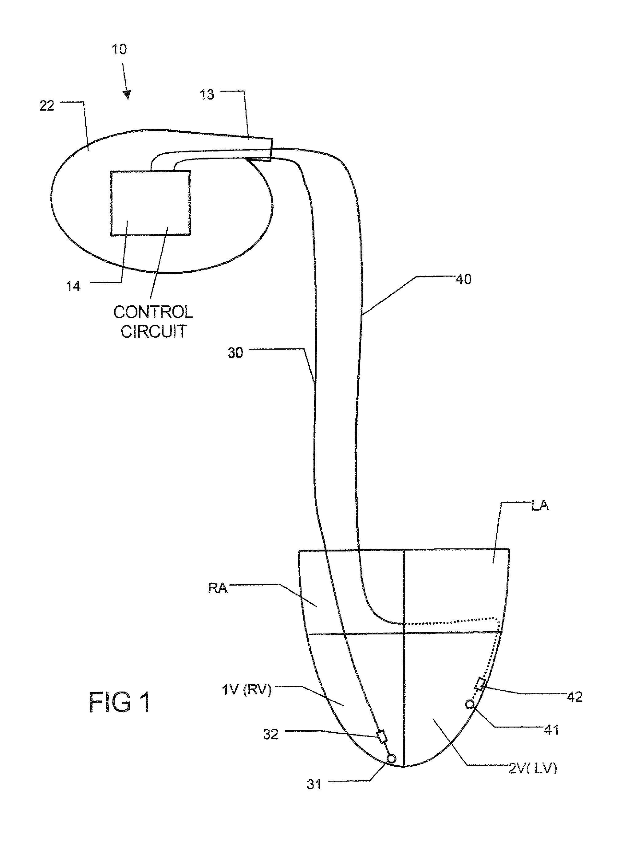
[0040]FIG. 1 schematically shows an implantable heart stimulating device 10 according to the invention. The device 10 has a housing 22. The housing 22 contains a control circuit 14. The device 10 also has a connector portion 13. Via the connector portion 13, the device 10 can be connected to different leads. In FIG. 1 the device 10 is connected to a first lead 30 and to a second lead 40. The device 10 together with the first lead 30 and the second 40 lead constitute an implantable heart stimulating system according to the invention. The first lead 30 includes a pacing tip electrode 31 and a sensing electrode pair 31, 32. In this shown example this electrode pair 31, 32 is a bipolar lead with a tip portion 31 and a ring portion 32. However, it is within of the scope of the invention to instead use unipolar leads, as is known to those skilled in the art. The second lead 40 has a corresponding electrode pair 41, 42.

[0041]FIG. 1 also schematically illustrates a heart with a right atrium...


PUM


Abstract

An implantable bi-ventricular heart stimulating device and system, suitable for treating congestive heart failure, have a control circuit with first and second pacing circuits and first and second sensing circuits. The device operates with time cycles corresponding to normal heart cycles. The control circuit determines: (a) whether a signal typical of an evoked response to a pacing pulse delivered by the first pacing circuit is sensed within a first time interval and (b) whether a signal typical for an R-wave transferred from the second ventricle, or from some other part of the heart, to the first ventricle is detected within a first time window. The operation of the device depends on whether the conditions (a) and (b) are fulfilled.

Description

BACKGROUND OF THE INVENTION[0001]1. Field of the Invention[0002]The present invention relates to an implantable heart-stimulating device with which it is possible to stimulate both the ventricles of a heart, i.e. a bi-ventricular pacemaker or defibrillator (pacer).[0003]The invention also relates to a system including such a device and to the use of the system.[0004]2. Description of the Prior Art[0005]Several different implantable devices for stimulating a heart are known. Such devices normally are able to sense electrical activity of the heart. Some implantable devices are able to deliver stimulation pulses to both the left and right ventricles of the heart, and sometimes also to the left and right atria.[0006]Devices that are able to deliver stimulation pulses to both the left and right ventricles are called bi-ventricular pacers. Such devices can be used to treat patients who suffer from different severe cardiac problems, e.g. patients suffering from congestive heart failure (CH...

Claims


Application Information

Patent Timeline
Patent Type & Authority Patents(United States)
IPC IPC(8): A61N1/368A61N1/37
CPCA61N1/368A61N1/3712A61N1/3684A61N1/36843
Inventor JARVERUD, KARINHOLMSTROM, NILSBJORLING, ANDERSUHRENIUS, ASAHEDBERG, SVEN-ERIKBUDGIFVARS, GORANSTRANDBERG, HANS
Owner ST JUDE MEDICAL
Why Eureka
Try Eureka