
Variable focal length deformable mirror

Active Publication Date: 2007-06-12
NAT TECH & ENG SOLUTIONS OF SANDIA LLC
View PDF6 Cites 46 Cited by
  • Summary
  • Abstract
  • Description
  • Claims
  • Application Information

AI Technical Summary

Benefits of technology

[0009]An on-axis variable focal length deformable mirror comprises a mirror plate having a reflective surface and a symmetry axis perpendicular to the plane of the mirror plate; an inner circular ring, centered on the symmetry axis, that simply supports and pushes axially on a side of the mirror plate; an outer circular ring, concentric with the inner circular ring, that simply supports and pushes axially on the opposite side of the mirror plate; and means for pushing on the inner circular ring in an axially opposed direction relative to the outer circular ring, while maintaining the planarity and parallelism of the rings, to provide a variable clamping force to the mirror plate and thereby deforming the mirror plate to provide an on-axis parabolic mirror shape.
[0011]Both the on-axis or off-axis deformable mirrors can have a concave or convex parabolic mirror shape. If the reflective surface is on the inner-ring-side of the mirror plate, a concave mirror is provided. If the reflective surface is on the outer-ring-side of the mirror plate, a convex mirror is provided. The mirror plate can be a deformable mechanical material, such as glass, metal, plastic, ceramic, or composite. In particular, the mirror plate can be a stock, round, coated or uncoated, flat optical blank that can be easily replaced if damaged. Internally cooled optics can also be used. The deformable mirror does not require expensive or elaborate non-planar grinding and polishing of an aspheric parabolic surface. The deformable mirror assembly does not require complicated apparatus, calibration, or control, and can be implemented at a low cost.
[0012]The mechanical geometry can be easily determined with a simple geometric algorithm requiring only inputs of focal length, off-axis angle, mirror plate diameter, and clear aperture. The deformable mirror can be easily designed with a nearly unlimited range of input parameters. A truly parabolic mirror shape can be obtained, enabling focusing without aberrations. Furthermore, because the deformable mirror can be built with small f-numbers, it can provide tight beam focusing.

Problems solved by technology

For example, ultrafast lasers and their applications rely heavily on broadband mirrors, because group velocity dispersion in refractive optics leads to pulse broadening, spectral distortions, and possibly beam breakup.
However, the spherical mirror has undercorrected spherical aberration for distant objects.
A disadvantage of most reflective optical systems is that there is generally a central obscuration that can affect the light throughput and image contrast (e.g., Cassegrain and Newtonian type telescopes in astronomy).
This leads to aberrations that are inherently present in all spherical optics.
However, because of their uniaxial character, aspheric parabolic surfaces are generally much more difficult and costly to fabricate than ordinary spherical surfaces.
Aspheric mirrors can be fabricated using computer-controlled diamond turning and traditional polishing methods, but material selection is limited and manufacturing costs can be large.
Fabricating off-axis aspheric surfaces is even more difficult.
While this method is feasible for small optics (e.g., 1-3 inch diameter) it becomes increasingly difficult to make large-angle, large-diameter off-axis parabolas.
The fabrication of larger off-axis angles is extremely expensive, because they require very big parent parabolas.
Furthermore, an as-machined mirror is not deformable and, therefore, does not enable variability of the focal length.
However, there are risks of fluid leakage and contamination of the mirror surface due to the pressurizing fluid, and the deformation provides a non-parabolic reflecting surface that is not optimum for many applications.
However, because the outer edge of the mirror plate is rigidly mounted to a housing in an axial holder, and not simply supported, a non-parabolic surface results.

Method used


Image

  • Variable focal length deformable mirror
  • Variable focal length deformable mirror
  • Variable focal length deformable mirror

Examples


Embodiment Construction

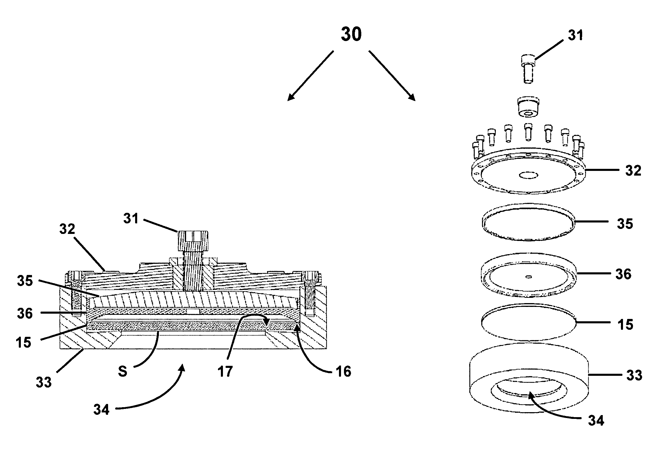
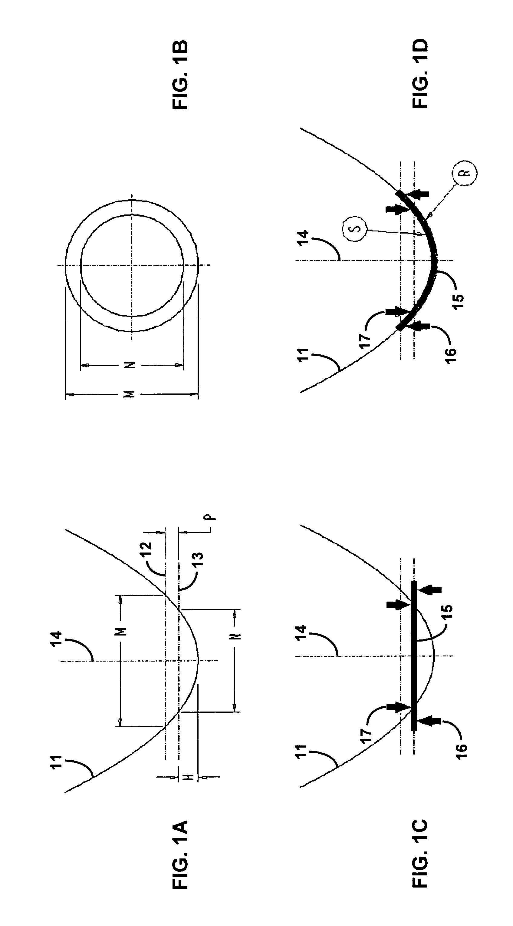
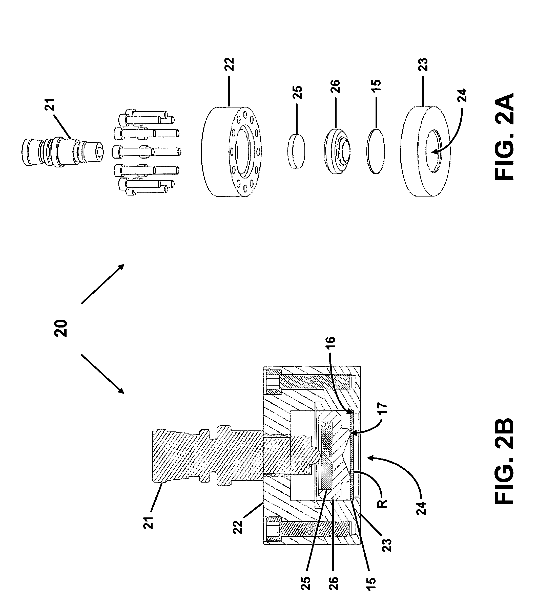
[0027]The present invention is directed to a variable focal length deformable mirror having a theoretically perfect parabolic reflective surface, and a method for forming the deformable mirror by deforming a planar mirror plate of uniform thickness. Such a truly parabolic shape ensures tight focusing, free of aberrations. The parabolic mirror shape is formed by placing the planar mirror plate between two circular or elliptical pushing rings, the geometry of which are defined by parallel paraboloid sections. The mirror plate is simply supported by the rings. Such a simple support supplies a displacement constraint, without imposing a rotation constraint or moment on the plate. A variable clamping force is applied to the rings, thus deforming the flat plate, and the focal length of the resulting parabolic surface is directly related to the pushing ring displacement. Using this simple geometric method, either concave or convex parabolic mirrors of arbitrary focal length and off-axis an...


PUM


Abstract

A variable focal length deformable mirror has an inner ring and an outer ring that simply support and push axially on opposite sides of a mirror plate. The resulting variable clamping force deforms the mirror plate to provide a parabolic mirror shape. The rings are parallel planar sections of a single paraboloid and can provide an on-axis focus, if the rings are circular, or an off-axis focus, if the rings are elliptical. The focal length of the deformable mirror can be varied by changing the variable clamping force. The deformable mirror can generally be used in any application requiring the focusing or defocusing of light, including with both coherent and incoherent light sources.

Description

STATEMENT OF GOVERNMENT INTEREST[0001]This invention was made with Government support under contract no. DE-AC04-94AL85000 awarded by the U.S. Department of Energy to Sandia Corporation. The Government has certain rights in the invention.FIELD OF THE INVENTION[0002]The present invention relates to deformable mirrors and, in particular, to a variable focal length concave or convex deformable mirror for on- or off-axis focusing.BACKGROUND OF THE INVENTION[0003]Reflective optics are finding increasing use in optical systems due to the transmission losses, chromatic aberrations, lower damage thresholds, and higher B-integral accompanying the use of refractive optics. For example, ultrafast lasers and their applications rely heavily on broadband mirrors, because group velocity dispersion in refractive optics leads to pulse broadening, spectral distortions, and possibly beam breakup. The simplest reflecting objective is the spherical mirror. However, the spherical mirror has undercorrecte...

Claims


Application Information

Patent Timeline
IPC IPC(8): G02B5/08G02B7/182
CPCG02B26/0825G02B5/10
Inventor HEADLEY, DANIELRAMSEY, MARCSCHWARZ, JENS
Owner NAT TECH & ENG SOLUTIONS OF SANDIA LLC
Features
  • Generate Ideas
  • Intellectual Property
  • Life Sciences
  • Materials
  • Tech Scout
  • Unparalleled Data Quality
  • Higher Quality Content
  • 60% Fewer Hallucinations
Learn More