Method of preventing abrupt voltage changes at the outputs of a pair of amplifiers and control circuit for a pair of amplifiers self-configuring in a bridge configuration

a technology of amplifiers and control circuits, applied in the direction of amplifiers, push-pull amplifiers, phase splitters, etc., can solve the problems of difficult dissipation of relatively large power, high operating temperatures, and difficult heat balance, and achieve the effect of preventing abrupt voltage changes

Active Publication Date: 2007-06-12
STMICROELECTRONICS SRL
View PDF8 Cites 11 Cited by
  • Summary
  • Abstract
  • Description
  • Claims
  • Application Information

AI Technical Summary

Benefits of technology

[0020]An object of the invention is to provide a method of preventing abrupt voltage changes at the outputs of a pair of amplifiers, and a common mode control circuit of a pair of amplifiers that address the above mentioned problems that affect multi-channel amplifiers in the presence of uncorrelated audio signals to be amplified.

Problems solved by technology

This may create heat balance problems.
For example, four 20 W amplifiers may have a power dissipation of about 4×12=48 W, and because of the limited space available in certain apparatuses, such a relatively large power may be difficult to dissipate without a significant increase of temperature within the apparatus.
Relatively high temperatures of operation may degrade the magnetic tape of cassettes or optical disks (CD), the drives of which are often tightly fitted inside a single apparatus case.
Unfortunately, switching amplifiers generate electromagnetic emissions (EMI) that in compact apparatuses interfere with the correct functioning of other systems, thus reducing their performance.
In fact, class AB power amplifiers are less efficient than switching amplifiers and a common technique for reducing power consumption of class AB amplifiers includes configuring them in a single-ended configuration instead of in a bridge configuration whenever it is possible to do so.
Unfortunately, it is not possible to use single-ended class AB amplifiers if the output surpasses this voltage because the output signal would be severely distorted by clipping.
The switching from a single-ended to a bridge output configuration and vice-versa may cause distortions and EMI disturbances in view of the fact that, when functioning with relatively low signal levels, one of the operational amplifiers of the bridge output structure is configured to operate as a buffer.
Although this approach is satisfactory when the signals in the different channels of the amplifier are substantially correlated among each other, the effectiveness in reducing the output step variations upon changing the configuration and the above-mentioned consequences diminishes significantly if the signals in the channels of the amplifier functioning in a bridge mode are no longer correlated.
It has been found that increased EMI and increased distortions occur when the correlation between the signals that are fed to the four channels of the audio system diminishes due to different settings of independent channel equalization controls that are customarily provided in quality car audio systems.
The independent equalization setting on the various channels cause different delays of propagation of signals through the channels, which thus become substantially uncorrelated.
These step variations are potentially dangerous because they may cause even an undue intervention of the protection circuit from short-circuits.
Even the power switch SW_C may turn on when it withstands is a high differential voltage, thus generating a cross-conduction current that is likely to cause the intervention of the protection circuit from short-circuits.

Method used


Image

  • Method of preventing abrupt voltage changes at the outputs of a pair of amplifiers and control circuit for a pair of amplifiers self-configuring in a bridge configuration
  • Method of preventing abrupt voltage changes at the outputs of a pair of amplifiers and control circuit for a pair of amplifiers self-configuring in a bridge configuration
  • Method of preventing abrupt voltage changes at the outputs of a pair of amplifiers and control circuit for a pair of amplifiers self-configuring in a bridge configuration

Examples


Embodiment Construction

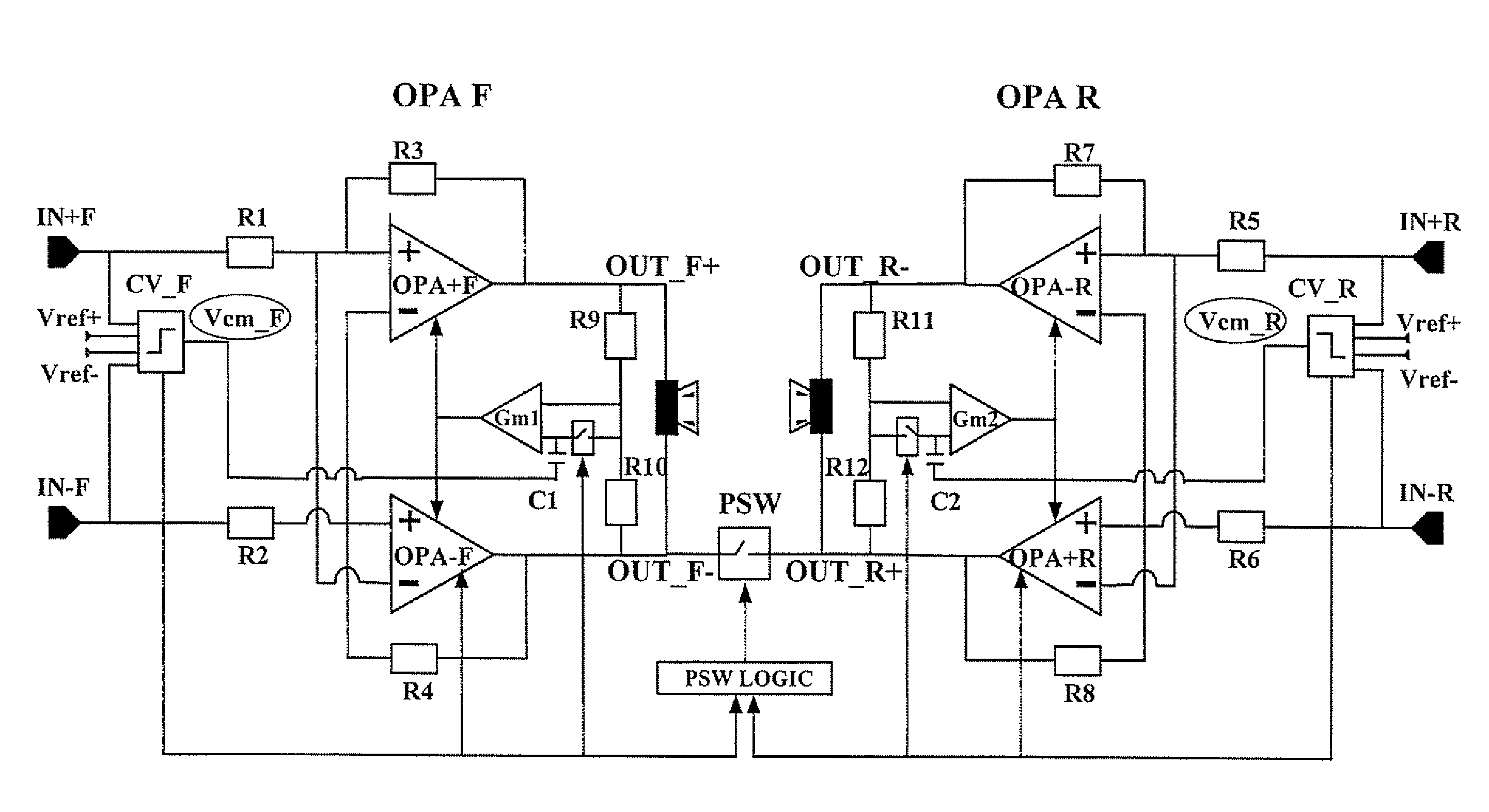
[0030]A detailed diagram of a bridge amplifier including a common mode control circuit formed in accordance with the invention is depicted in FIG. 4. R1 . . . R12 are resistors and the block PSW_LOGIC contains the logic circuitry that controls the power switch PSW.

[0031]The general architecture of this bridge amplifier is similar to that of the prior art amplifier of FIG. 2, but the storage capacitors C1 and C2 are not referenced to a ground potential as in the prior art circuit. On the contrary, the storage capacitors C1 and C2 are referenced to voltages VCM_F and VCM_R, respectively, which are a saturated replica of the respective input signal.

[0032]In the example, these voltages VCM_F and VCM_R are purposely generated by the differential / single-ended converters CV_F and CV_R, respectively, and range within the same voltage levels VREF+ and VREF− that define the comparison window of the input differential signals within which the amplifier is in a single-ended configuration. When ...


PUM


Abstract

A common mode control circuit reduces abrupt voltage changes at the outputs of a pair of amplifiers which, in turn, reduces EMI and distortions that occur when the correlation between the signals fed to the four channels of an audio system diminishes. The common mode control circuit generates for each amplifier a reference potential that is a saturated replica of the respective differential input signal of the amplifier that saturates when the amplifier switches to a bridge configuration.

Description

FIELD OF THE INVENTION[0001]The present invention relates in general to amplifiers with a reduced power consumption such as for car radio and hi-fi audio applications, and in particular, to a method of preventing abrupt voltage changes at the outputs of a pair of amplifiers, and to a common mode control circuit implementing this method.BACKGROUND OF THE INVENTION[0002]In many applications and primarily in audio reproduction systems such as car radios, hi-fi audio systems and similar apparatuses that are intrinsically compact because of stringent installation requirements, as well as in portable apparatuses, power dissipation in the final power stages is often quadrupled to drive a pair of loudspeakers (front and rear) for each stereo channel. This may create heat balance problems. For example, four 20 W amplifiers may have a power dissipation of about 4×12=48 W, and because of the limited space available in certain apparatuses, such a relatively large power may be difficult to dissi...

Claims


Application Information

Patent Timeline
Patent Type & Authority Patents(United States)
IPC IPC(8): H03F3/45H03F1/14H03F3/00H03F1/02H03F1/32H03F3/30H03F3/68
CPCH03F1/0277H03F1/32H03F3/3081H03F3/45475H03F3/68H03F2200/03H03F2200/114H03F2203/45138
Inventor CHELLI, FABIOBRAMBILLA, DAVIDE
Owner STMICROELECTRONICS SRL
Why Eureka
Try Eureka