Hydrogen generator and fuel cell system comprising the same

a fuel cell and hydrogen generator technology, applied in electrochemical generators, combustible gas production, lighting and heating apparatus, etc., can solve the problems of complex manufacturing steps, small size of hydrogen generators, and high requirements for parts manufacturing precision, and achieve high heat efficiency, simple configuration, and high evaporation capability

Inactive Publication Date: 2007-06-19
PANASONIC CORP
View PDF6 Cites 8 Cited by
  • Summary
  • Abstract
  • Description
  • Claims
  • Application Information

AI Technical Summary

Benefits of technology

[0024]The present invention has been made under the circumstances, and an object of the present invention is to provide a hydrogen generator having a simple configuration, high evaporation capability, and high heat efficiency.
[0026]In such a configuration, the water absorbing member provided in the tubular space can improve an evaporation capability. Therefore, the water reserved in the evaporator during start of the hydrogen generator is quickly evaporated. Consequently, the start time of the hydrogen generator can be reduced.
[0027]In addition, since the steam can be supplied to the reformer stably, load fluctuation or the like can be easily dealt with.
[0045]In accordance with the hydrogen generator of the present invention, the evaporation capability can be improved and loss of heat emission can be reduced, using a simple configuration.

Problems solved by technology

This makes the hydrogen generator small-sized.
This makes manufacturing steps complex.
In addition, manufacturing precision of parts requires strictness.
Consequently, manufacturing cost becomes high.

Method used


Image

  • Hydrogen generator and fuel cell system comprising the same
  • Hydrogen generator and fuel cell system comprising the same
  • Hydrogen generator and fuel cell system comprising the same

Examples


Embodiment Construction

[0061]Hereinafter, an embodiment of the present invention will be described with reference to the accompanying drawings.

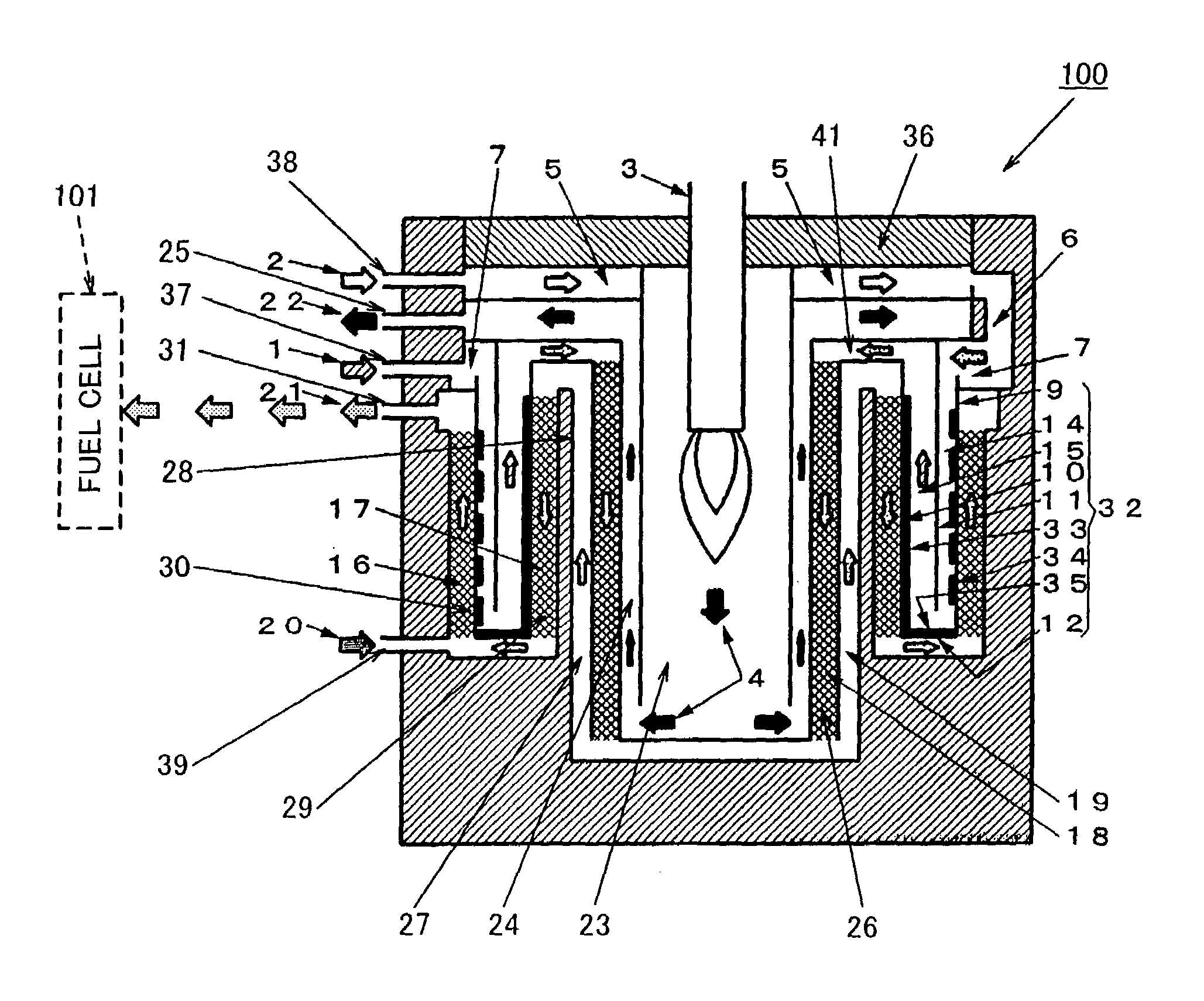
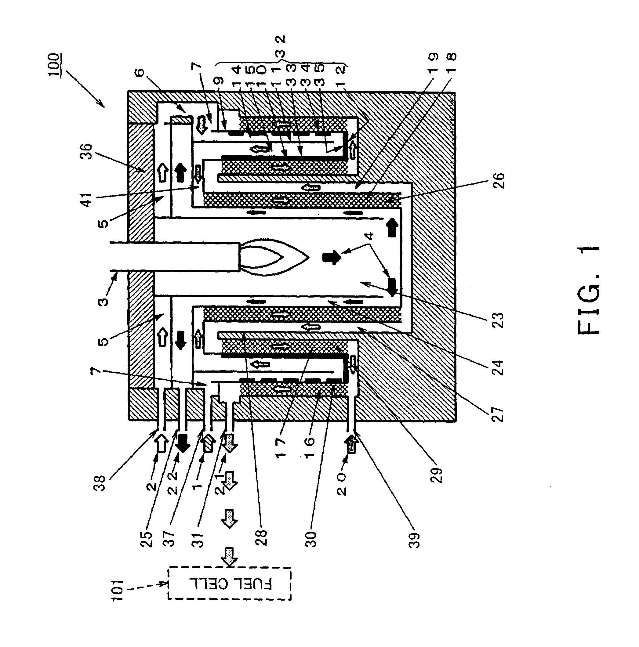
[0062]FIG. 1 is a cross-sectional view schematically showing a configuration of a hydrogen generator of the present invention. As shown in FIG. 1, a hydrogen generator 100 comprises a burner 3 configured to generate a combustion gas 4 and a cylindrical combustion chamber 23 provided below the burner 3. On an outer peripheral side of the combustion chamber 23, a tubular combustion gas flow passage 24 is provided coaxially with the combustion chamber 23 to allow the combustion gas 4 generated by the burner 3 to flow from downward to upward. The combustion gas flow passage 24 is connected to an exhaust gas outlet 25 formed on an upper portion of a side face of the hydrogen generator 100. The combustion gas 4 flowing through the combustion gas flow passage 24 is discharged from the exhaust gas outlet 25 as an exhaust gas 22.

[0063]In addition to the exhaust gas outlet 2...


PUM

PropertyMeasurementUnit
temperatureaaaaaaaaaa

Abstract

A hydrogen generator comprises a burner for generating a combustion gas, a reformer provided around the burner to generate a reformed gas containing hydrogen by a steam reforming reaction based on a feed material comprising a compound containing at least carbon and hydrogen and a steam, using heat transmission from a combustion gas generated by the burner, and an evaporator having an inner tube provided around the burner, an outer tube provided around the inner tube, and a bottom plate that closes a lower portion of a tubular space formed between the inner tube and the outer tube, the evaporator being configured to evaporate water supplied to the tubular space to generate a steam to be supplied to the reformer, wherein a water absorbing member having a water absorbing capability is provided in the tubular space.

Description

BACKGROUND OF THE INVENTION[0001]1. Field of the Invention[0002]The present invention relates both to a hydrogen generator configured to generate a reformed gas by reacting a compound containing carbon and hydrogen with water and supply the reformed gas to a fuel cell configured to generate a power using hydrogen, and to a fuel cell system comprising the hydrogen generator.[0003]2. Description of the Related Art[0004]In general, a steam reforming reaction is employed as a method of generating hydrogen to be supplied to a fuel cell. The steam reforming reaction is to react a city gas and a steam as a feed material using a ruthenium catalyst at a high temperature of approximately 600° C. to 800° C. to generate a reformed gas containing hydrogen as a major component.[0005]FIG. 12 is a cross-sectional view schematically showing a configuration of the conventional hydrogen generator disclosed in Japanese Laid-Open Patent Application Publication No. 2002-187705. The hydrogen generator in ...

Claims


Application Information

Patent Timeline
Patent Type & Authority Patents(United States)
IPC IPC(8): B01J7/00B01J8/04C01B3/38C01B3/48H01M8/06
CPCB01J8/0465B01J8/0496C01B3/384C01B3/48H01M8/0612H01M8/0662B01J2208/00309B01J2208/00504B01J2208/0053C01B2203/0233C01B2203/0283C01B2203/044C01B2203/047C01B2203/066C01B2203/0816C01B2203/0866C01B2203/1294C01B2203/82H01M8/0618Y02E60/50B01J8/04H01M8/06
Inventor TAMURA, YOSHIOMUKAI, YUJIMAENISHI, AKIRAASOU, TOMONORI
Owner PANASONIC CORP
Why Eureka
Try Eureka